Chapter 3. Installing Güralp 5U sensors
3.1 Unpacking and packing
The 5U accelerometer is delivered in a single cardboard box with foam rubber lining. The packaging is specifically designed for the 5U and should be reused whenever you need to transport the sensor. Please note any damage to the packaging when you receive the equipment, and unpack on a clean surface.
The package should contain:
the accelerometer
a signal connection cable (if ordered)
a suitable connector.
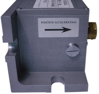
The sensor serial number label can be found on the lid of the sensor. If you need to request the sensor production history, you will need to quote either the serial number of the sensor or the works order number, which is also provided on the calibration sheet.
3.2 Initial testing
To test the 5U before installation, you will need a DC power source which can deliver 100 mA at 10 to 12 V and a digital voltmeter (DVM) with 1 and 10 V ranges. Connect the supplied cable, ensuring that it is connected with the correct polarity (see the instrument's pin-out in section 5.1).
Caution: You should never supply more than 12.5 V to the 5U.
To make it easier to measure the output from the sensor, you can use the 5U hand-held control unit or a improvised interface box, which can be manufactured from a screw clamp connector block. This will simplify the connections to the appropriate connector pin outputs.
Place the 5U sensor on a flat surface with the POSITIVE ACCELERATION arrow horizontal.
Switch on the power supply.
Connect the voltmeter to pins J and K of the output connector (corresponding to the low gain vertical component.) Measure the output of the low gain vertical component. The steady output voltage should be about zero (± 10 mV). If it is not, centre the instrument as described in section 3.4.
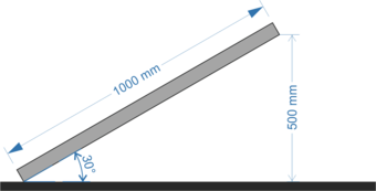
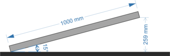
Now follow the instructions appropriate to the sensitivity of your 5U as shown in the table below. The correct tilt angles can be achieved by placing the instrument on a board that can be lifted at one end, as shown. The reading on the voltmeter should be close to that shown in the final column:
Full-scale | Procedure | Reading |
±2 g | Turn the sensor on its side, so that the POSITIVE ACCELERATION arrow points upwards. | -5.00 V |
±1 g | Tilt the sensor so that the POSITIVE ACCELERATION arrow points 30° upwards from the horizontal.
| -5.00 V |
±0.5 g | Tilt the sensor so that the POSITIVE ACCELERATION arrow points 15° upwards from the horizontal.
| -5.18 V |
±0.1 g | Tilt the sensor so that the POSITIVE ACCELERATION arrow points 3° upwards from the horizontal.
| -5.23 V |

If the performance so far has been as expected, the instrument may be assumed to be in working order and you may proceed to install for trial recording tests.
3.3 Installing the sensor
Caution: If you are in any doubt about how to install the sensor, you should contact Güralp Systems.
The Güralp 5U can be installed for vertical or horizontal sensitivity. In either case, it can be mounted to a vertical or to a horizontal surface. An optional clamp-block is available which allows mounting to poles or cables. Consult the following diagrams to determine the correct mounting method for your application:
Vertical sensitivity, vertical mounting surface
Vertical sensitivity, horizontal mounting surface
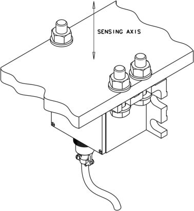
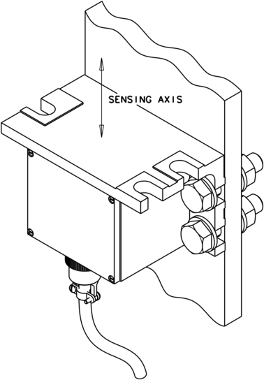
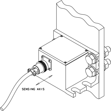
Horizontal sensitivity, vertical mounting surface
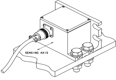
Horizontal sensitivity, horizontal mounting surface
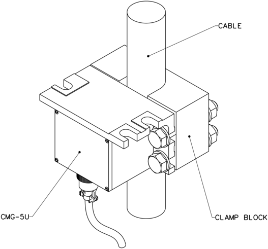
Cable or pole mounting, using optional clamp-block
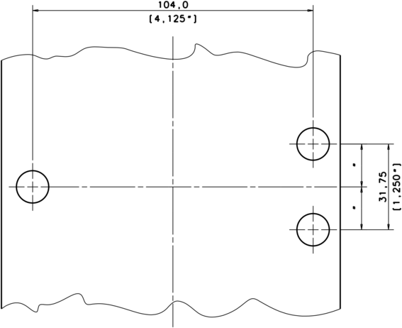
Mounting holes in the mounting surface should be drilled as shown below. M12 or ½ inch hexagonal mounting bolts are preferred but it is also possible to use M10 or ⅜ inch bolts. You may find it useful to copy the footprint of the sensor base onto a metal sheet to use as a template when drilling fixing holes into the surface where you want to mount the sensor.
Regardless of the mounting arrangement, proceed to install the instrument as follows:
Fasten the instrument to the mounting surface using three bolts or an appropriate clamp as previously described.
Fix the sensor to the mounting surface, with the POSITIVE ACCELERATION arrow pointing in the required direction. The accelerometer has no levelling feet, but can use internal simulated level adjustment to compensate as long as it is fixed to a hard, clean surface within 1 degree of the horizontal.
The direction of sensitivity the instrument is marked on the outside of the unit, with the arrow pointing towards the positive sensor output orientation. If this arrow is horizontal, the sensor will be responsive to horizontal signals; likewise, if the arrow points upwards, the sensor will respond to vertical ground acceleration (with positive output corresponding to an upwards ground movement.)
Although converting a sensor from horizontal to vertical response involves compensating for the acceleration due to gravity, you do not have to zero the sensor manually. The sensor output offset adjustment is carried out electronically by emulating the shift in mass position. You can then calibrate the offset using a potentiometer within the unit, without any loss of dynamic range.
If required, make a screening box for the sensor, to shield it from draughts and sharp changes of temperature. A suitable box can be constructed from expanded polystyrene slabs (e.g. 5 cm building insulation slabs) with sealed joints between them and a hole drilled for the connector. You can then use high-grade glass fibre sealing tape to fix the leads in position, and fasten the box to the mounting surface. Commercial duct sealing tape is ideal.
Connect the sensor to the analogue input of the Güralp digitiser using the cable provided, or to another recording device using a cable made up as described in section 3.5.
3.3.1 Installation in Hazardous environments
The fully enclosed aluminium case design of the 5U instrument makes it suitable for use in hazardous environments where electrical discharges due to the build up of static charge could lead to the ignition of flammable gasses. To ensure safe operation in these conditions, the metal case of the instrument must be electrically bonded ('earthing') to the structure on which it is mounted, forming a path to safely discharge static charge.
Where electrical bonding ('earthing') is required during the installation of a 5U instrument, the central mounting hole that extends through the instrument should be used as the connection point. This is electrically connected to all other parts of the sensor case. Connection can be made by either a cable from a local earthing point terminated in a 8 mm ring tag or by the mounting bolt itself.
3.4 Centring the 5U
Once installed, you should centre the instrument ready for use.
Note: The range of the offset adjustment is greater than 1 g equivalent, so that instruments can be used horizontally or vertically. This means that, for more sensitive instruments, such as 0.1 g versions, there will be large parts of the adjustment range where the signal is at positive or negative full scale.
Begin monitoring the output signal of the sensor using a digitiser or digital voltmeter, as described in section 3.2.
Remove the pressure release cap and insert a thin screwdriver or pot-adjuster into the hole.
Locate the small potentiometer screw head just inside, and turn it in one direction or another until the output voltage is reading zero.
Replace the pressure cap to keep the instrument's electronics protected from water and dust.
After the cover is installed, the accelerometer outputs may drift until the system establishes temperature equilibrium with its environment and the sensor settles down in its position. If required, the offset adjustment can be repeated to achieve a better output offset. With experience, it should be possible to reduce the output level to less than ±1 mV.
3.5 Electrical connections
3.5.1 Power supply
The Güralp 5U is normally powered directly from the digitiser through the 10-way connector, although you can use a separate 12 V DC power supply if you wish (again, a custom cable will be required). In this case, the positive output from the power supply should be connected to pin B with the power supply ground connected to pin A.
The current consumption from a 12 V supply is about 53 mA. An isolated DC–DC converter installed inside the sensor housing forms the main part of the 5U's power supply; its filtered outputs provide the ±12 V required to operate the sensor electronics. The DC–DC converter is protected against polarity reversal.
Caution: You should never supply more than 12.5 V to the 5U.
3.5.2 Signal outputs - Standard (low-gain) and High-gain
The Güralp 5U sensor has two separate outputs, one with low gain and one with high gain. The straight-through cable provided will connect the low gain outputs to the digitiser input (see section 5.1). To make use of the high-gain signal, you will need to make up a cable connecting the high-gain pins (C and G) of the sensor to the digitiser input pins (J and K). The sensor outputs have an output impedance of 47 Ω, which is low compared to the input impedance of the digitiser., which is typically between 47 kΩ and 1 MΩ.
The low and high gain output lines are differential outputs balanced about signal ground so that either differential drive or single-ended drive is available. For a single-ended drive, the signal ground must be used as the signal return path and the non-inverting (positive) acceleration output must be interfaced to the recorder.
Caution: You must not ground any of the active output lines, as this would allow damaging currents to flow through the output circuits.
If you have two analogue inputs available on a connected digitiser, you could make up a three-way cable which connects both high and low gain outputs to the digitiser.
Caution: You should not attempt to connect both outputs of the 5U to the same digitiser input port.
3.5.3 Calibration signal input
The calibration signal input is referenced to the signal ground. It can be connected directly to the digitiser's calibration output line or to a signal source of your own. A typical amplitude for a calibration signal is ±10 Volts.
3.5.4 Calibration enable
The Güralp 5U is available with either an “active low” or an “active high” calibration enable input. This should be specified when ordering. If the instrument is to be used with Güralp Systems' digitisers, “active low” should be chosen.
3.5.4.1 Active low versions
The calibration enable input is TTL-level and is tied high by an internal pull-up resistor. To activate calibration, this input should be connected to signal ground. During normal operation (i.e. when not calibrating) it should either be left floating (disconnected) or connected to a high impedance output.
3.5.4.2 Active high version
The calibration enable input is TTL-level and is tied low by an internal pull-down resistor. To activate calibration, this input should be connected to a voltage source of +5 to +10 V DC with respect to signal ground. The input presents an impedance of around 10 kΩ . During normal operation (i.e. when not calibrating) it should either be left floating (disconnected) or connected to a high impedance output.