Chapter 5. Operation
5.1 Installation overview
These steps make up the installation procedure. Detailed instructions follow in subsequent sections.
Unpack the accelerometer system from the reusable container (See quick start). Save the shipping box for possible future use.
Prepare the mounting surface.
Mount the levelling baseplate to the CMG-5TD.
Orient the CMG-5TD using the orientation pointers.
Anchor the baseplate to the mounting surface.
Level the CMG-5TD.
Install the GPS receiver providing a clear view of the sky, and connect it to the CMG-5TD using the GPS cable.
Connect the CMG-5TD to a PC running Scream
Connect the power supply (12 to 36 V DC) to the grey/blue power/data cable
Switch on the power and view the acceleration time series using Scream.
Using a DVM, check and adjust the CMG-5TD offsets if required.
Cover the sensor with a polystyrene cover for long term thermal stability. The cover will act as a thermal shield from draughts. Position the polystyrene box carefully so that it does not touch the sensor package.
5.2 Installation method
The surface should have a scribed north/south orientation line accurately surveyed from reliable markers. Mount the concrete anchor into the mounting bench, around the middle of the orientation line. Loosely attach the mounting (lower) portion of the levelling plate to the concrete anchor, using the bolt provided. Attach the upper portion of the levelling plate to the base of the CMG-5TD using the screws provided. Finally, attach the CMG-5TD to the mounting base by joining the two portions of the levelling plate using the socket-cap screws provided.
5.3 Installation in hazardous environments
The fully enclosed aluminium case design of the 5T instrument makes it suitable for use in hazardous environments where electrical discharges due to the build up of static charge could lead to the ignition of flammable gasses. To ensure safe operation in these conditions, the metal case of the instrument must be electrically bonded ('earthing') to the structure on which it is mounted, forming a path to safely discharge static charge.
Where electrical bonding ('earthing') is required during the installation of a 5T instrument, the central mounting hole that extends through the instrument should be used as the connection point. This is electrically connected to all other parts of the sensor case. Connection can be made either via a cable from a local earthing point terminated in a 8 mm ring tag or via the mounting bolt itself.
5.4 Orientation
Use the handle and north indicator inscribed in the handle to orient the CMG-5TD.
5.5 Levelling
Use the large socket-cap screws to level the CMG-5TD. Remove the upper portion of the mounting plate, then tighten down the concrete bolt, securing the base. Re-attach the upper portion of the mounting plate to the CMG-5TD. Check orientation and level and then tighten down the levelling locking nuts.
5.6 Power supply considerations
The CMG-5TD will operate from 12-36 V DC. The CMG-5TD draws around 185 mA from a 12 V power supply.
5.7 Connections
Connect the GPS receiver to the CMG-5TD using the cables provided.
Connect the DE9 connector of the grey/blue power/data cable to a PC or communications device.
Connect the power supply (12 to 36 V DC) to the bare ends of the grey part of the grey/blue power/data cable. The red core should go to the positive terminal or the terminal marked '+' and the black core should go to the negative terminal or the terminal marked '-'. The power supply should be capable of sourcing 200 mA.
5.8 Offset adjustment
When the instrument is installed in it’s final position and correctly aligned, the approximate level should be checked using the bubble level on the top of the casing. The bubble should lie completely within the scribed ring. To check the DC offsets, read the RIC value for each acceleration stream in the SCREAM window. No adjustment is necessary if these values are less than or equal to ±5000 counts.
To adjust the DC offsets, remove the screwed cover protecting the adjustment screws, as shown in the diagram below.

Warning: GSL instruments are assembled at near to sea level. When using the instrument at altitude, there may be a considerable pressure differential between the air inside the casing and the external atmosphere. This could cause the sealed cap to fly off with considerable force when initially released. Take care that this does not cause injury.
Selecting the channels in turn, adjust the level screws to reduce the RIC values to less than ±5000 counts, repeating until consistent results are obtained on all three channels. When offset adjustment is complete, replace the protective cover firmly.
It is likely that, after the cover is installed, the accelerometer outputs will drift until the system establishes temperature equilibrium with it’s environment and the sensor settles down in its position. If required, the adjustment can be repeated to achieve a better (lower) output offset. With experience, it should be possible to reduce low acceleration output levels to about ±5000 counts or less.
5.9 Configuration and control using Scream
Scream is a free software application for Windows and Linux PCs. For more information and download details, please see www.guralp.com/scream/.
The CMG-5TD may be configured using Scream's graphical interface. Right- click on the digitiser's icon in the source tree and select “Configure” from the pop-up menu. Using this dialogue, you may interactively set the digitiser's system characteristics, control the output of streams at different digitisation rates and set output baud rates and digitiser buffering parameters.

Alternatively, using terminal emulation software, such as PuTTY, minicom or Hyper Term, you can access the digitiser's command line and send commands directly to the built in CMG-DM24 digitiser.
This mode may also be invoked from Scream by right-clicking on the digitiser's icon and selecting Terminal from the pop-up menu. When using standard terminal programs, you must initiate command mode by typing 

Parameters from most of the commands are stored to the battery-backed CMOS and only take effect when the digitiser is rebooted. When you click the “Download” button from the digitiser configuration interface, the parameters you have chosen are transferred to the digitiser and it is automatically rebooted. You will notice a data gap in the traces in the Waveview window corresponding to the digitiser you have rebooted. This occurs because the reboot automatically clears the data buffer and resets the output block counter.
To access the digitiser configuration dialogue from Scream, double-click on the digitiser's icon in the Available Streams window (NOT the Local or COM port icons). Alternatively, you can right-click on the digitiser's icon and then select “Configure” from the pop-up menu.
The following sections correspond to the different tabs available in the configuration dialogue.
5.9.1 System ID
System Identifier and Serial Number: The digitiser type is identified by its system identifier and serial number. These two parameters are stored as the first two 32-bit fields in the header of each data and status block generated by the digitiser, in order to indicate the block's origin. Each of these parameters consists of 6 alphanumerics encoded as base 36 numbers. On delivery from the factory, the system identifier and the serial number are, respectively, set to the GSL works order number and the seismometer’s serial number. Either parameter can be reset to any convenient combination of letters and numbers, such as an abbreviation of your institution and the deployment site code.
Sensor Type: This field will be pre-programmed at the factory for the proper sensor type (CMG-5T).
GPS Type: The digitiser can utilize time signals from different sources. Options available are NMEA (Garmin or Trimble) GPS receivers or stream synchronization. When using stream synchronization, time signals from a GPS antenna are sent via telemetry from a central site to the digitiser. In order to synchronize with the time standard in use, the correct option must be selected.
5.9.2 Output control
Sampling rate: The output of the digitiser’s analogue-to-digital converters (ADC) is sampled at 2 kHz. These data are filtered and reduced to lower rates using a digital signal processor (DSP). The DSP has four cascaded filter/decimation stages, each of which can be programmed for decimation factors of ÷2, ÷4, ÷5, ÷8 or ÷10. The output of each stage is called a “tap”. Each stage may be configured for a different decimation factor.
The four text-fields on the left of the Output Control tab allow you to select the sampling rates for each of the four digitiser taps. Each of the taps must have a sampling rate lower than the one above but the rate must be achievable using decimation by a factor of 2, 4, 5, 8 or 10. Each drop-down menu offers a list of the rates that are permitted, given the sampling rate on the line above it.
If some of the outputs are not required, leave the check-boxes clear in order to reduce communications bandwidth requirements.

Stream selection: The digitiser has three channels or streams. These are depicted by the three columns labelled Z, N and E in the Output Control window shown above.
A tick in a box will give an output for the corresponding channel (column) at the corresponding sample rate (row). For each sample rate there are two possible rows to tick. The upper row for each sample rate will give a continuous output at that sample rate; the lower row, shown diagrammatically as passing through a switch, will only output data when its trigger criteria are met (see below).
The Stream IDs displayed in the main Available Streams window have six-character ID’s. The first four characters identify the digitiser and the last two characters identify the stream from the digitiser. The first of these two characters identify the channel, while the second defines the ‘tap’, or digitiser output ( see Data Transmission Protocol & Data Block Structure later).
For example; for the Output Control configuration shown above, there will be three data streams, Z, N and E, providing continuous data at 100sps, 20sps and 2sps. This is shown below, where the digitiser ‘1123’ has the following streams:-
Z2, N2, E2 are input channels Z, N, E output through the second tap ‘2’;
Z4, N4, E4 are input channels Z, N, E output through the third tap ‘4’,
Z6, N6, E6 are input channels Z, N, E output through the fourth tap ‘6’,
00 is the digitiser status stream (notice that there is no sample rate)
(Odd tap numbers (1, 3, 5, …) are used for streams from a second instrument.)

For each tap there are two rows of check-boxes where the user can tick either triggered or continuous data outputs. The digitiser applies a simple short term average (STA) ÷ long term average (LTA) algorithm and/or an absolute level (counts) algorithm to a selected stream or set of streams to determine whether the trigger condition is met. These streams may be bandpass filtered before evaluation using standard bandpass parameters. The data transmitted due to the trigger may be from different streams than those used to determine the trigger.
For this to function properly, triggering streams must be selected and trigger criteria must be set by clicking on the Trigger button . When at least one stream is selected for triggered output, selection of triggering streams and trigger criteria are enabled. It is possible to trigger from one tap but record data from one or several different taps.

5.9.3 Triggering
Once at least one box is checked for triggered output, the Triggering box and tab are activated. If you set triggering, you must also set the parameters for the trigger criteria.

The Data Source button selects the tap (streams) that will be evaluated for triggers for both the STA/LTA and the Level triggers. In general, it is not advisable to use an STA/LTA trigger directly from broadband data. The Bandpass Filter button allows the user to select from a set of standard bandpass filters from a pull-down menu (a full list of options is given later in the STA/LTA chapter). The chosen filter will be applied to the streams from the triggering components before they are tested for the trigger condition.
The corner frequencies of the pass band of the filter are determined by the Nyquist frequency, which is given by the sampling rate of the triggering data. The three filter options have pass bands between 10% and 90%, between 20% and 90% and between 50% and 90% of the data’s Nyquist frequency, respectively.
Trigger criteria: Trigger criteria for the STA/LTA and Level triggers function may be set in the Trigger Setup window, accessed by clicking on the Trigger button near the bottom of the Output Control window.
The three tick boxes down the left side of the windows (Z, N, E) allows the user to choose the channels (for the specified tap) which will be tested for a trigger condition.
STA/LTA parameters: The user sets the parameters by clicking on them. Typically, the time interval for the short term average should be about as long as the signals you want to trigger on, while the long term average should be taken over a much longer interval. Both the STA and LTA values are recalculated continually, even during a trigger.
The system declares a trigger when any one of the triggering components exceeds this value. The trigger ratio is continuously recalculated for all components and the system will only cancel the trigger condition when all the components selected for triggering have fallen below their respective ratio values.
The user can also specify the pre-trigger and post-trigger data intervals. These values determine the minimum length of data that will be saved prior to the trigger condition, and how much data will be saved after the trigger condition has lapsed. Triggered streams will always start and end on integer seconds.
If the box “Common Values” is ticked, a trigger parameter entered for one component will be used for all selected components. (BANDPASS, STA, LTA, RATIO, PRE-TRIG and POST-TRIG).

Level triggering parameters: The user specifies the Data Source, channels and levels by clicking on them, similar to the STA/LTA settings. The levels are specified in counts.
5.9.4 Baud rates

This tab allows the setting of the line speed for the main serial output.
It is possible to set different rates for transmission and reception but this is rarely required with modern communications equipment. Ticking the “Identical Tx/Rx rates” check-box simplifies the dialogue.
A line speed of 115,200 Baud is adequate for the highest sample rates that the instrument can generate. It may be necessary to reduce the line speed if the data are to be passed over a modem or wireless link.
The “Stop Bits” drop-down menu should be left at 1 unless your communications equipment requires a different value.
5.9.5 Data flow
The digitizer operates in one of several transmission modes. These modes relate to how the unit uses its Flash memory:
as a simple data store, from which you can request data (FILING and DUAL modes);
as a buffer holding unacknowledged blocks, which are transmitted in preference to real-time data (FIFO mode);
as a buffer holding unacknowledged blocks, which are transmitted whenever the transmission is free but no real-time data blocks are ready (ADAPTIVE mode);
not at all (DIRECT mode).
Separate from these modes are buffering modes, which tell the unit what to do when its Flash memory becomes full: either
carry on, overwriting the oldest data held, or
stop writing and switch the digitizer into DIRECT mode.
You can switch between filing modes in Scream! by right-clicking on the digitizer and clicking on Control..., then navigating to the Data Flow pane:

To choose a transmission or buffering mode, choose options from the Transmission Mode or Buffering drop-down menus, and click Apply. An explanation of the chosen mode is displayed beneath each menu. The following sections also explain the filing modes available.
The Buffering legend also displays the amount of Flash memory present in your digitizer. In the example screen-shot above, this is 64 Mb.
To clear the Flash memory of the digitizer, click the Reset-flash button. You will be asked for confirmation before the memory is cleared.
At the bottom of the tab is a line describing the current state of the digitizer's memory pointers. You can use this line to check that data are being written into memory. Select Auto-Refresh to make the line update automatically.
5.9.5.1 DIRECT

Instructs the digitizer not to use Flash memory for storage. Instead, all data are transmitted directly to clients. An instrument in DIRECT mode still honours the GCF Block Recovery Protocol: a temporary RAM buffer always holds the last 256 blocks generated, and if a client fails to receive a block it can request its retransmission.
If you expect breaks in communication between the instrument and its client to last more than 256 blocks, or if you want the instrument to handle breaks in transmission (rather than relying on the client to request missed blocks), you should use
ADAPTIVE mode, if you want data to stay as near to real time as possible (but do not mind if blocks are received out of order) or
FIFO mode, if you need blocks to be received in strict order (but do not mind if the instrument takes a while to catch up to real time.)
5.9.5.2 DUPLICATE

Instructs the DM24 to transmit streams directly to clients as for DIRECT mode, but also to store all data into Flash storage as for FILING mode. If a client fails to acknowledge a block, the digitizer does not attempt to retransmit it.
Heartbeat messages are not sent in DUPLICATE mode.
5.9.5.3 FILING

Instructs the digitizer not to transmit blocks to clients automatically, but to store all digitized data in the Flash memory. If you have chosen the RECYCLE buffering mode (see below), the memory is used in circular fashion, i.e. if it becomes full, incoming blocks begin overwriting the oldest in memory. If the WRITE-ONCE mode is active, the instrument will switch to DIRECT mode (see above) when the memory becomes full.
Heartbeat messages
When in FILING mode, an instrument transmits “heartbeat” messages over its data port. These short messages take the place of data blocks, and ensure that programs such as Scream! know that an instrument is present.
If your digitizer is in FILING mode, Scream! will displays a slider at the bottom of the tab. Moving this slider changes the interval between heartbeat blocks.
You can tell Scream! to download new data automatically whenever it receives a heartbeat message from an instrument in FILING mode. This is useful, for example, in autonomous installations connected by intermittent modem links. To enable this feature:
Choose File → Setup... from Scream!'s main menu, and navigate to the Recording pane.
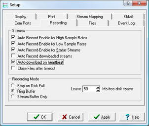
Check Auto-download on heartbeat.
Click OK.

Using FILING mode with Auto-download on heartbeat ensures that Scream! receives all new data whenever it can, regardless of the configuration of any devices between you and the instrument.
5.9.5.4 DUAL

Instructs the digitizer to transmit any continuous streams directly to clients as for DIRECT mode, but to store triggered data into Flash storage as for FILING mode.
If you choose DUAL mode but do not select any continuous streams for output, the instrument will send heartbeat messages as for FILING mode. Scream! can pick these up and download new data as necessary.
5.9.5.5 FIFO (First In First Out)

Instructs the digitizer to begin writing blocks to Flash memory as for FILING mode, but also to transmit data to clients. Data are transmitted in strict order, oldest first; the digitizer will only transmit the next block when it receives an explicit acknowledgement of the previous block.
If the communications link is only marginally faster than the data rate, it will take some time to catch up with the real-time data after an outage. If you want data to be transmitted in real-time where possible, but are worried about possible breaks in communication, you should use ADAPTIVE mode instead.
FIFO mode will consider a data block successfully transmitted once it has received an acknowledgement from the next device in the chain. If there are several devices between you and the instrument, you will need to set up the filing mode for each device (if applicable) to ensure that data flow works the way you expect.
Like all the filing modes, FIFO mode does not delete data once they have been transmitted. You can still request anything in the Flash memory using Scream! or over the command line. The only way data can be deleted is if they are overwritten (in the RECYCLE buffering mode, see below) or if you delete them manually.
5.9.5.6 ADAPTIVE

Instructs the digitizer to transmit current blocks to clients if possible, but to store all unacknowledged blocks in the Flash memory and re-send them, oldest first, when time allows. ADAPTIVE mode is best suited for “real-time” installations where the link between digitizer and client is intermittent or difficult of access.
If the communications link is only marginally faster than the data rate, it will usually be busy transmitting real-time data. Thus, it may take a while for the instrument to work through the missed blocks. In this case, and if your client supports it, you may prefer to use the Block Recovery Protocol to request missed blocks where possible.
Some software packages (most commonly Earthworm) cannot handle blocks being received out of time order. If you are using such a package, ADAPTIVE mode will not work, and may crash the software.
5.9.6 Buffer Memory Usage
5.9.6.1 RE-USE / RECYCLE
Instructs the digitizer to carry on using the current filing technique when the Flash memory becomes full, overwriting the oldest data held. This buffering mode is called RECYCLE in Scream!
For example, in DUAL mode with RECYCLE buffering, the latest continuous data will be transmitted to you as normal, and the latest triggered data may be retrieved from the Flash memory using Scream! or the digitiser's command line. However, if you do not download data regularly from the Flash memory, you may lose older blocks. This mode thus lets you define the end point of the data held by the instrument.
5.9.6.2 WRITE-ONCE
Instructs the digitizer to stop writing data to the Flash memory when it is full, and to switch to DIRECT mode automatically.
For example, in FIFO mode with WRITE-ONCE buffering, the station will transmit data to you continuously, but also save them in the Flash memory until it is full. Once full, the instrument will switch to DIRECT mode and continue transmitting, though no further data will be saved. This mode thus lets you define the start point of the data held by the instrument.