Chapter 2. Equipment Overview
2.1 Introduction
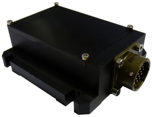 The Güralp Systems 54T is an extremely compact, robust accelerometer based on micro-electro-mechanical systems (MEMS) technology, suitable for civil engineering, hazard mitigation and structure monitoring applications.
The MEMS sensors are mounted in an environmentally sealed case and can measure simultaneously the North/South, East/West and vertical components of ground motion over a wide frequency range. It is ideally suited for permanent installations in locations with medium noise.
Because there are no moving parts, no mechanical clamping is required and the instrument is ready to record ground movements as soon as you provide it with power. The instrument can operate in any orientation but this may limit the output range (see section 4.4).
Each instrument is delivered with a detailed calibration sheet showing its serial number, output type and factory-measured sensitivity.
2.2 Features
Three orthogonal axes of acceleration with high dynamic range
Compact, hard anodized aluminium case
Full-scale sensitivity of ±2 g or ±4 g
Highly robust - with no moving parts
Frequency response to DC as standard
Military-specification locking bayonet connector
Optional cables available for connection to all Güralp Systems digitizers
Complements Güralp Systems feedback accelerometers for high-density, high performance arrays
Simple installation - bolts directly to any flat surface
Please refer to Appendix B on page 10 for full specifications.
2.3 Build options
The Güralp 54T is supplied in two standard build versions:
±2 g: Nominal sensitivity is 1 V/g with an output of 2.5 V at 0 g
±4 g: Nominal sensitivity is 0.5 V/g with an output of 2.5 V at 0 g
The standard instrument has three single-ended (non-differential) outputs which provide voltages in the range zero (full scale negative acceleration when orientated normally) to five volts (full scale positive acceleration when orientated normally). Use of the voltage outputs is described in section 4.1.
There are also three versions available which provide current outputs. The available options are:
0-20 mA outputs (10 mA at 0g)
4-20 mA outputs (12 mA at 0g)
0-40 mA outputs (20 mA at 0g)
Use of the current outputs is described in section 4.2.
The build option for any individual sensor is marked on the identification label.
2.4 Ports and Connections
A single nineteen-pin military-specification bayonet connector provides both power to the instrument and the analogue data outputs from the sensors.
Refer to Appendix A on page 9 for information on connector pin-outs.