Chapter 6. Inside the 3TB
6.1 The sensors
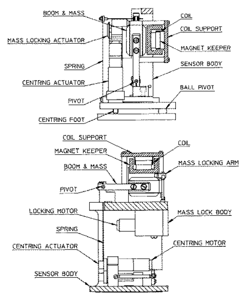
The horizontal and vertical sensors are similar in design. The inertial mass in both cases consists of a transducer coil and a leaf-spring suspended boom which swings on a frictionless hinge. A triangular spring supports the weight of the mass; in the vertical sensor this spring is pre-stressed, with a natural period around 0.5 s, whilst the horizontal sensor has an unstressed flat spring with a natural period around 1 s. 3TB sensors have no spurious resonances below 140 Hz, and weigh around 180 g. The small boom size and stiff springs allow three independent instruments to be mounted within the casing, together with all the associated feedback electronics.
The sensor and hole-lock units are stacked one on top of the other with a set of accurately-machined stacking tubes, which also form part of the sensor's pressure housing. Fixing holes provided on each end face allow for simple and accurate assembly. The base of each unit includes a double “O” ring to isolate the sensor from any pressure variations in the atmosphere.
The 3TB functions by monitoring the position of each mass with a capacitative position sensor. The three sensors are identical. Signals from the sensors are fed into an electronic processing unit, which is mounted in a screened compartment above the mechanical components (see below for details on the feedback circuitry.)
When the instrument is being transported, the masses are locked securely in their frames so as to relieve strain on the support hinges. This locking is performed by a small motor-driven clamp in response to a signal from the surface controller unit.
Before using the instrument, the boom of the vertical sensor must be levelled and the bases of the horizontal sensors tilted, so that the masses are centred in their equilibrium positions. These adjustments are made by small DC motors controlled remotely.
See section 4, “Installing the 3TB in a borehole” for detailed instructions on how to set up your 3TB installation.
The signal voltages output by the 3TB are proportional to ground velocity, and are transmitted from the instrument on balanced differential lines. In addition, mass position signals are sent as single-ended circuits referred to analogue ground on the output plug. The 3TB also receives control signals, which are used to clamp and un-clamp the masses, and to run the motors which level and centre the instrument once in position. Finally, a line is provided for you to apply a calibrating voltage to the force transducers, thereby measuring the deflection sensitivity.
6.2 The control system
The internal operations of the 3TB are supervised by a control microprocessor, which drives the mass clamping and centring adjustment motors. It responds to commands sent on three input lines by grounding one (to digital ground) for 0.2 – 7 seconds.
The signals you can send to the microprocessor are termed LOCK, UNLOCK, and CENTRE. Each command acts on the vertical, N/S and E/W masses in turn. The microprocessor prevents the system from attempting incompatible actions (e.g. centring when the masses are clamped.)
While a command is taking place, the BUSY LED will flash; you can use this for diagnostic purposes. See the description of each command for full details.
When no command is active, i.e. all three lines are high, the control microprocessor goes into a power-saving mode. In routine operation, the lines are controlled from the break-out box, Hand-held Control Unit or digitizer. If you send control signals to the 3TB manually, you must ensure that the lines are allowed to float high after sending the signal, or the equipment may be damaged. A “biased-OFF” type switch can be used for this purpose.
6.2.1 LOCK
This command unlocks the masses and clamps the horizontal sensors by tilting them up to their end stops.
If LOCK is activated when the masses are already locked, the processor will unlock them and attempt to lock again. This is useful if you suspect that the locking procedure has failed.
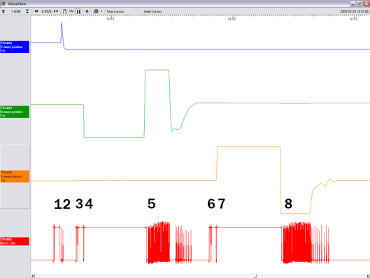
In detail, the process acts as shown in the following graph. The top three streams are the mass position outputs of each component (Z, N/S and E/W, respectively), whilst the bottom one represents the state of the BUSY LED (up = on).
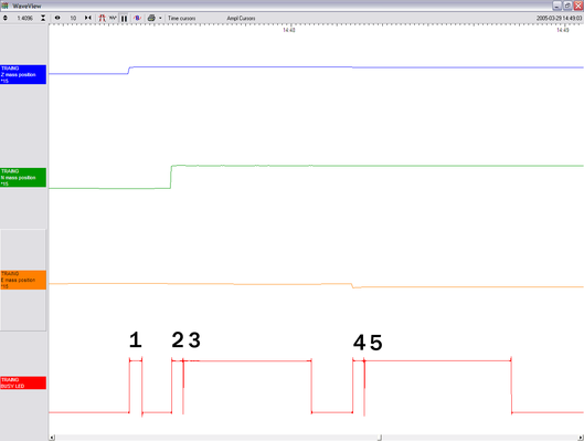
In the five-stage process, each mass in turn is locked with a motorised micrometer (stages 1, 2, 4), and the N/S and E/W sensor bases are tilted to their end stops (stages 3 and 5). At some point during each tilting stage, the position of the relevant mass will flip to one or other side.
The BUSY LED is lit during each stage, but goes out briefly between stages, allowing you to follow the progress of the lock.
6.2.2 UNLOCK
This command unlocks the sensor masses and prepares the instrument to begin operating.
If UNLOCK is activated when the masses are already unlocked, the processor will lock them and attempt to unlock again. This is useful if you suspect that the locking procedure has failed.
During the UNLOCK procedure, the instrument automatically performs a round of centring for each component.
Again, you can use the BUSY LED to monitor the progress of unlocking.
The instrument checks to see whether the vertical mass is locked, and unlocks it if necessary.
The vertical mass is centred by applying pulses to the motor. This stage is often very short, since the vertical mass is locked near its central position.
The instrument checks the N/S sensor and base, and unlocks the sensor.
The N/S sensor base is tilted to its level position. This process takes rather longer. At some point during this stage, the mass may flip to the other side (as seen in the green trace.)
The N/S sensor mass is centred by applying pulses to the motor. This stage will take longer than stage 2, since it must move the mass all the way from its end stop. As the mass nears the centre, the control circuit spaces out the pulses.
The E/W component is checked and unlocked.
The E/W sensor base is tilted to its level position as in step 4.
The E/W sensor mass is centred as in step 5.
After unlocking, the instrument automatically performs a round of centring (see below).
6.2.3 CENTRE
This command re-centres the masses. If the masses are clamped, or if the sensor mass positions do not exceed ± 1.2 V, the CENTRE command does nothing. Otherwise, it attempts to zero the output of the vertical, N/S and E/W sensors in sequence by exerting small extra forces on the boom. For the vertical sensor, a motor-driven adjuster presses a small spring lever against the boom until the mass position sensor indicates an offset close to zero. In the case of the horizontal sensors, the sensor frame is tilted on its base plate. Again, the controller monitors the mass position sensor and stops the centring process once it reaches its lowest offset.
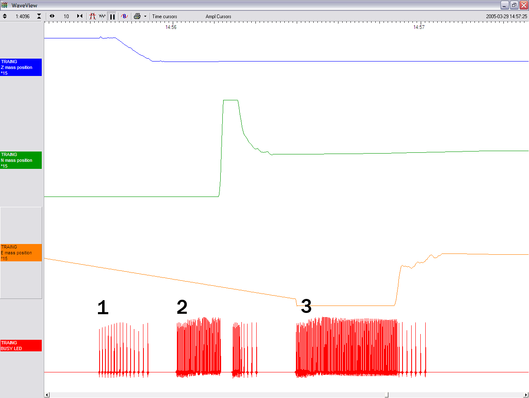
This graph shows a typical centring process:
The BUSY LED pulses to indicate that it is centring the Z component. Each pulse corresponds to a small force on the mass. The pulses become more spaced out as this goes on, until a pulse is missed, signifying that no corrective impulse is needed.
The N/S component follows in the same way. The mass position output does not change for a while, as the true mass position is outside the range of the output. In this case, the pulses cause the mass to overshoot the central position, and a second group of pulses in the opposite direction is applied to bring it into line.
The E/W component follows in the same way. All three masses are now centred and the process completes.
After the sensor unlocks the masses, the first round of centring has to move the N/S and E/W components all the way from their end stops, whilst the Z component is often closer to the proper position. Because of this, the first Z centring operation takes much less time than the others, and you may not notice it.
After successful centring, the mass position outputs should be in the range 0.1 – 0.8 Volts. If the centring process leaves the mass position outputs above ±1.1 Volts, you should start another centring cycle by activating the CENTRE command again. You will probably need to initiate the centring process several times before the masses are adequately centred.
6.3 The feedback system
The output from a modern broadband seismometer does not depend on the natural characteristics of the instrument. Instead, the period and damping of the sensor are completely determined by a feedback loop which applies a force to the sensor mass opposing any motion. The force required to restrain the movement of the mass can then be used to measure the inertial force which it exerts as a result of ground motion.
All Güralp 3 series units are based on these general principles. The capacitative position sensor for each mass produces a voltage proportional to the displacement of the mass from its equilibrium position. After amplification, this voltage generates a current in the force transducer coil which tends to force the mass back toward equilibrium. The feedback loop has a sufficiently high gain to cancel the motion of the mass. Since the mass is not moving, the forces acting on it must be balanced; the feedback voltage then directly measures the force, and hence the acceleration, which is being applied to the mass. The feedback loop introduces a phase shift, which must be carefully controlled if the instrument is to remain stable over its entire frequency range. This is achieved using compensation components in the forward and feedback paths.
Force feedback seismometers of this type rely on the assumption that the force transducer produces a field of constant strength. The magnetic circuit and magnet/pole assembly in the 3TB are designed so that the field strength from the feedback transducer is constant over large deflections and current levels. Tests have shown that the mechanical suspension system and electronics of a 3TB instrument are linear to better than 107 dB (source: measurements made at ASL during evaluation for the USGS National Network.)
In a feedback seismometer with a displacement transducer, it is essential to monitor the acceleration (mass position) output. This provides the position of the displacement transducer and therefore also the mass position, as the displacement transducer is attached to the sensor inertial mass. The sensor should always be operated with the displacement transducer centred or nulled, so that the response to input acceleration is linear.
There are two types of feedback system which can be used in a 3TB instrument, known as hybrid and conventional-response feedback.
6.3.1 Hybrid feedback
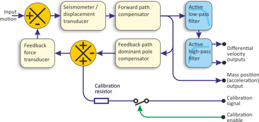
The hybrid feedback circuit contains a single capacitor in parallel with a resistor, resulting in a single dominant pole at 0.033 Hz (30 s). Below this frequency, the response of the seismometer is flat to ground acceleration; above it, the response is flat to velocity. (Other values for the acceleration-velocity corner can be provided upon request.) Hybrid-feedback systems provide a stable response, particularly for portable systems, with a high saturation level at high frequencies and a high dynamic range at long periods.
An active low-pass filter provides a high-frequency cut-off point at a frequency you specify. Without the filter, the velocity response is flat up to 100 Hz. Outside the feedback loop there is an active high-pass filter with a corner frequency of 0.01 Hz (100 s) or 0.005 Hz (200 s), which serves to remove any DC offsets.
6.3.2 Conventional-response feedback
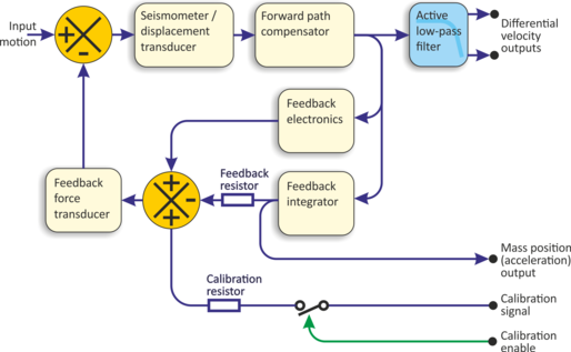
The conventional-response feedback system has an additional parallel feedback circuit, consisting of a non-inverting integrator in series with a resistor. This arrangement results in two poles at specified frequencies. The velocity response of a conventional-response system is defined by a transfer function identical to that of a conventional long-period sensor with a damping constant ζ of 0.707 (1/√2)
The seismometer can be supplied with an equivalent resonant frequency of 0.033 Hz (30 s), 0.01 Hz (100 s) or 0.0083 Hz (120 s) as required. An active low-pass filter provides a high-frequency cut-off point at a frequency you specify.
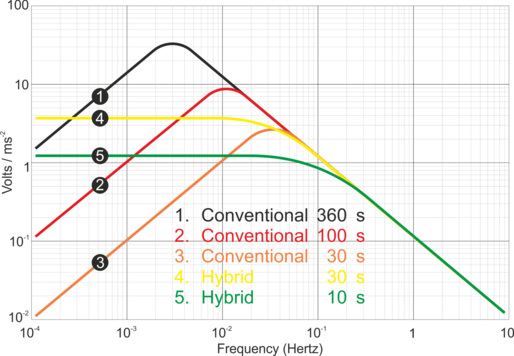
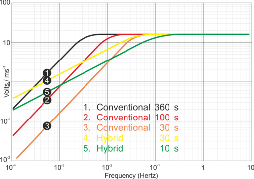
6.3.3 Comparisons
The figures below plot the comparative response of a conventional velocity output broadband sensor and a hybrid output broadband sensor. The upper graph shows the response in terms of output against input acceleration in units of V/ms-2, whilst the lower graph is plotted in terms of output against input velocity, in V/ms-1.