Chapter 2. First encounters
2.1 Unpacking and packing
The 3V and 3ESPV seismometers are delivered in a single transportation case, with the sensor system and hole lock mechanism (if ordered) packed separately. The packaging is specifically designed for the instrument and should be reused whenever you need to transport it. Please note any damage to the packaging when you receive the equipment, and unpack on a clean surface. The package should contain:
the seismometer;
a cable to join the sensor to the surface control box;
the surface control unit;
the hole lock control unit, if ordered;
a cable strain relief mechanism, if ordered;
a Handheld Control Unit (HCU) for monitoring sensor outputs and calibration, if ordered;
an inclinometer monitor box;
a calibration data sheet;
this manual.
2.2 Handling notes
The 3V and 3ESPV are sensitive instruments, and is easily damaged if mishandled. It should not be operated until it has been securely installed in a borehole casing. If you are at all unsure about the handling or installation of the device, you should contact Güralp Systems for assistance.
Do not bump or jolt any part of the sensor when handling or unpacking.
Keep the sonde sections vertical wherever possible. Carry them by hand and store in a safe rack. Never drag or roll the sonde.
Never lay the sonde horizontally whilst the sensors are unlocked. If the sensor system topples over, you must inform Güralp Systems.
Keep all the parts of the sensor system protected and clean so that they can be joined together securely. Store in the original packaging if possible.
Do not kink or walk on the data cable (especially on rough surfaces such as gravel), nor allow it to bear the weight of the sensor.
Do not connect the instrument to power sources except where instructed.
2.3 Assembling the instrument
The instrument is delivered in separate sections, which need to be assembled before it can be installed in a borehole. It is recommended that you perform these steps with the help of at least one other person.
Important: Make sure your environment is clean and dust free before assembling the unit. Stray fibres or particles cause damage to the “O”-ring seals between the components and may render the sensor unusable. Do not remove the protective caps on the ends of each unit until you are ready.
Ensure that the top surface of the hole lock and the base of the sensor are clean.
Carefully lift the sensor, and connect the cable from the hole lock to the connector on the sensor base.
Gently lower the sensor onto the hole lock, making sure that it is properly aligned and no wires are trapped beneath the base.
Using the cap head screw provided, fasten the sensor base onto the hole lock.
2.4 Control units
The 3V and 3ESPV are operated from the surface through various control units. All the instrument functions can be accessed through one or other unit. Most can be removed from the site once the instrument is ready for use.
Some of these control units are optional and may not have been supplied with your installation. Their functions can be duplicated either by applying voltages directly to control lines (see appendixes for pinout information) or through a connected Güralp digitizer such as the CMG-DM24. The DM24 digitizer is able to pass commands to the instrument from a Data Communications Module (DCM) or a computer running Güralp Systems' Scream! software, allowing you to access all of the instrument's functions remotely.
The breakout box is normally placed where the signal cable emerges from the borehole. It provides connectors for attaching the various other control units, supplies power to the instrument and relays output signals to a recorder or digitizer.
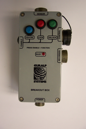
The SENSOR connector is a 32-way mil-spec plug, and should be connected to the borehole instrument with the cable provided.
The RECORDER connector is a 26-way mil-spec plug. This should be connected to an analogue data recorder or stand-alone digitizer. In systems using downhole digitizers, this is replaced by a 10-way mil-spec serial connector for attaching to a Data Communications Module (DCM), modem or other communications link.
The CONTROL connector is a 26-way mil-spec plug intended for connecting to an external controller or Handheld Control Unit, with the same pin out as the RECORDER connector.
The POWER connector is a 10-way mil-spec plug, which should be connected to a source of 12 – 30 V DC power, for supplying to the borehole instrumentation. When operating the hole lock, you should connect the Holelock Control Unit to this connector. Because of the high voltages employed, the hole lock circuitry is entirely isolated from the rest of the electrical systems in the sensor and surface unit; it is not usual to power the sensor whilst using the hole lock.
For deep-borehole installations (over 50 m) we recommend that you use a breakout box with internal line drivers, to ensure that logic signals are reliably transmitted to the sensor. Contact Güralp Systems for advice.
Note: The breakout box looks very similar to other Güralp breakout boxes. However, its internal wiring is different from that used for some other instruments. For this reason, if you are using several instrument types, you should mark each breakout box clearly so that it is always used with the correct instrument.
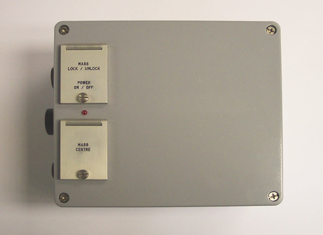
Most newer 3V and 3ESPV units have state-of-health (SOH) electronics installed within the sensor housing, which manage the instrument's mass control functions. In some installations, however, these electronics are installed at the surface, in a dedicated control unit. This unit provides the same connectors as the breakout box, but is rather larger. In addition to the SOH electronics, it contains a differential input to differential output amplifier, and a fuse to protect the internal DC–DC converter against polarity reversal. Its connectors are the same as those on the breakout box, except that
POWER and HOLELOCK POWER are brought out on separate 10-pin connectors, and
the SENSOR connector is a 32-pin mil-spec plug, with a straight-through cable to the sensor.
The surface control unit is supplied with a 3 m cable as standard. This can be extended up to 100 m without compromising signal quality. The sensor uses amplifiers with high common mode rejection to ensure the signal to noise ratio is maintained over this distance. Individually shielded twisted-pair cabling must be used for the sensor outputs, control lines and power supply. If you need to make up a suitable cable, you should confirm the cable type with Güralp Systems.
The push-button switches which operate the sensor's control commands (mass locking, unlocking, and centring) are housed beneath waterproof lids. You must release the fixing screws holding the lids down before you can initiate any commands.
To calibrate the instrument, the Calibration enable line must be activated. This operates a relay which allows a calibration signal to flow through the transducer feedback coil. This provides an extra force acting on the sensor masses, producing a corresponding deflection in the output signal, which can be analysed by a control computer to extract the seismometer's response characteristics.
Most Güralp instruments are manufactured with active-low Calibration enable lines. However, instruments with active-high calibration can be manufactured on request.
The instrument is delivered with its sensor mass locked, so that they will not be damaged in transit. You should lock the mass whenever you need to move the instrument.
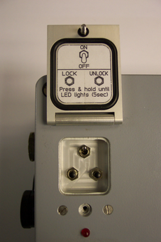
To unlock the instrument, hold down the ENABLE and UNLOCK buttons (or the UNLOCK switch on a surface control unit) for at least six seconds. The sensor's microcontroller will free the mass and ready it for use. Once this is done, the controller automatically starts a centring cycle. If you issue an UNLOCK command when the mass is already free, the instrument will attempt to lock the mass first, and then unlock it in sequence as normal.
To lock the instrument, hold down the ENABLE and LOCK buttons (or the LOCK switch) for at least six seconds. The sensor's microcontroller will lock the vertical sensor mass. The instrument is now protected against accelerations up to 10g, and is ready for transportation.
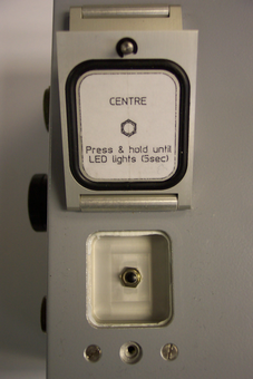
To centre the instrument, hold down ENABLE and CENTRE buttons (or the CENTRE switch) for at least six seconds. If the masses are locked, the microcontroller will do nothing. Otherwise, it attempts to zero the output of the sensor. Inside, a motor-driven adjuster presses a small spring lever against the boom until the mass position output indicates an offset close to zero.
After successful centring, the mass position outputs should be in the range 0.1 – 0.8 V. If the centring process leaves the mass position outputs above ±1.1 V, start another centring cycle. You will probably need to perform several rounds of centring before the masses are ready.
This portable control unit provides easy access to the seismometer's control commands, as well as displaying the output velocity and mass position (i.e. acceleration) on an analogue meter.
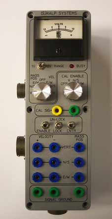
The HCU provides
two identical 26-pin connectors for attaching to the HCU or RECORDER connectors of the Surface Control Unit, and
a 10-pin connector through which you can power the instrument, if desired. The power pins on this connector are directly connected to those on the SENSOR POWER connector of the Surface Control Unit. When using this alternative power connection, you should ensure you do not inadvertently connect two power supplies together.
The upper section of the HCU contains a simple voltmeter for monitoring various signals from the instrument.
To monitor the velocity output, switch the dial to V VEL.
To monitor the mass position output, switch the dial to V MASS POS.
You can set the range of the meter with the RANGE switch. When switched to 10 V, the meter ranges from –10 to +10 V (as marked.) When switched to 1 V, the range is –1 to +1 V.
You can calibrate a 3V or 3ESPV sensor through the HCU by connecting a signal generator across the yellow and green CALIBRATION SIGNAL inputs and turning the CAL ENABLE dial to V. The sensor's response can now be monitored or recorded, and calibration calculations carried out.
The section of the HCU below the calibration lines controls the instrument's mass control system. To initiate locking, unlocking, or centring, hold down the ENABLE switch on the HCU together with the appropriate switch for the command you want to issue for at least six seconds.
The remainder of the HCU provides useful connections for each of the signal lines from the instrument, for attaching to your own equipment as necessary.
The borehole sensor system can operate successfully in boreholes with a tilt angle up to 3.5 °. To check that the instrument is installed suitably close to the vertical, a two-axis inclinometer is installed within the sensor housing. The inclinometer monitor unit is used as a visual guide to the sensor's tilt only, and should not be used if precise attitude information is required. You should check the inclination of the instrument before unlocking the sensor masses, since too great a tilt can damage the components.
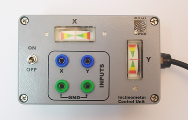
To measure the attitude of a 3V or 3ESPV instrument:
Connect the inclinometer monitor unit to the CONTROL connector of the surface control unit.
Switch the ON/OFF switch on the monitor unit to the ON position. The inclinometer is powered separately from other parts of the system; this switch provides power to the downhole circuitry as well as to the monitor unit. The inclinometer should not normally be powered up whilst the sensor is in use.
Read off the X and Y components of the tilt from the analogue meters.
If both tilts are within the green shaded region, the instrument is close enough to vertical that it can be levelled and centred successfully. If either output is in the red shaded region, you should not attempt to unlock or centre the sensor masses. Instead, if possible, you should move the instrument within the borehole to a place where it can lie closer to vertical.
If you need to use the outputs of the inclinometer for some other purpose, you can also connect a multimeter to the banana sockets on the inclinometer monitor unit.
2.5 Operating the hole lock
The hole lock, if fitted, can be extended and retracted using the hole lock control unit:
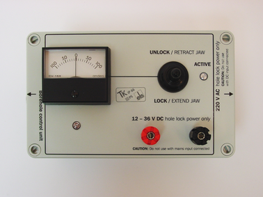
Caution: The hole lock may be using high-voltage mains (outlet) power.
Connect the hole lock control unit to the HOLELOCK POWER connector of the surface control unit, and to a mains power supply. Alternatively, connect a 12 – 24 V DC power supply across the input terminals of the hole lock control unit. Do not connect both DC and mains power at the same time.
The hole lock control unit supplied in regions with 220 V AC mains power differs from that supplied for 110 V AC mains power. You should ensure that you provide the correct voltage to the hole lock control unit, otherwise damage may result to the sensor.
If you are supplying power to the sensor through another connector, ensure that it is switched off whilst you operate the hole lock.
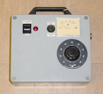
If you are using a deep-borehole hole lock control unit, set the dial to zero.
To extend the jaw of the hole lock:
Hold the switch on the hole lock control unit in the EXTEND JAW or + position. If you are using a deep-borehole control unit, there will be an additional dial compared to the unit pictured; turn this until the built-in ammeter reads around 0.1 A.
When the arm makes contact with the borehole casing, the current will drop slightly. Continue holding the switch in the EXTEND JAW position.
When the lock arm reaches its fully extended position, the motor will automatically stop and the current will drop to 0 A. If using a deep-borehole unit, return the dial to zero.
If the current has not dropped quite to zero after 30 – 40 s of operation, release the switch, wait a few seconds, and push it back to the EXTEND JAW position briefly. If the arm is not completely extended, you will see a surge of current. If the current remains constant, the jaw is at its maximum reach.
Once the sensor is locked in place, it is recommended that you remove the hole lock power cable and control unit from the site. Without power, the hole lock will not be able to retract, and the sensor will be secure.
To retract the jaw of the hole lock:
Tension the load bearing cable, to take up any slack.
Hold the switch on the hole lock control unit in the RETRACT JAW or – position. If using a deep-borehole control unit, also turn the dial until the built-in ammeter indicates 0.3 – 0.5 A. More current is drawn retracting the arm, because the motor is now working against the spring.
When the lock arm reaches its fully retracted position, the motors will automatically stop and the current will drop to 0 A. If using a deep-borehole unit, return the dial to zero.
If you prefer, you can operate the hole lock by applying voltages directly to the sensor.
To extend the jaw, connect the Hole Lock Motor pin on the sensor (or on the Surface Control Unit's HCU or RECORDER connectors) to a +12 V power source, and the Hole Lock Motor Return pin to 0 V.
To retract the jaw, reverse the polarity so that the Hole Lock Motor Return pin is at +12 V and the Hole Lock Motor pin is at 0 V.