Chapter 3. Installing in a borehole
Before installing any instrument in a borehole, it is recommended that you prepare the installation site so there is clear access all around the hole.
Keep the borehole capped at all times except when inserting or removing the instrument, so that debris and tools do not accidentally fall in.
Lay out the cables beside the borehole, or set up a cable drum nearby, so that they do not become tangled.
Ensure the tripod is tall enough to hang the entire installation (sensor and strain relief unit or digitizer) from it, with the sensor off the ground.
Use a winch with a depth gauge if possible, or measure out the cable beforehand.
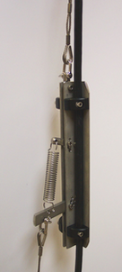
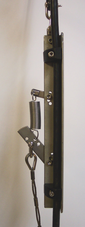
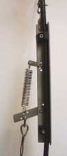
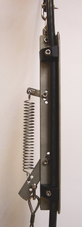
Most installations are equipped with a strain relief unit, which consists of a metal arm that swings out from the load-bearing cable to wedge against the side of the borehole. This removes any strain in the load-bearing cable and prevents vibrations from the surface from being transmitted to the instrument. In installations with a downhole digitizer, the strain relief arm is fitted to the base of the digitizer sonde; the phrase “strain relief unit” in the following instructions should be taken to refer to the digitizer's strain relief arm.
3.1 Installing a sensor with hole lock unit
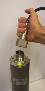
Connect the signal cable to the connector on top of the sensor. Ensure that the “O”-rings inside the housing are clean, and tighten the knurled connector nut to its end stop.
If applicable, you should test the hole lock mechanism before installing the sensor. For safety reasons, the hole lock is normally supplied with the arm extended.
To test the mechanism, connect the signal cable to a surface Control Unit and Holelock Control Unit, and attempt to retract the hole lock arm (see Section 2.5, page 19.) If this fails, you should contact Güralp Systems. Extend the arm once more.
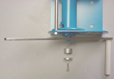
Fix the main lifting cable to the shackle on top of the strain relief mechanism, and run the signal cable through the mechanism using the built-in clamps (without tightening them.) Do not allow the signal cable to bear any of the sensor's weight.
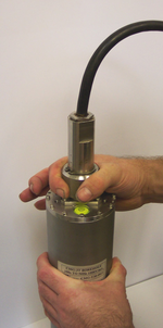
Attach the lifting loop to the sensor using four M5×16 screws (provided).
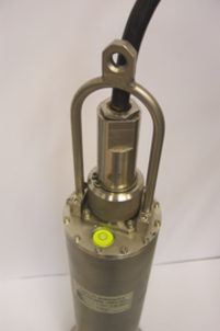
Join the loop to the bottom of the strain relief mechanism using the linking cable provided.
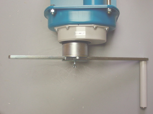
Using a small winch, hoist up the sensor package and strain relief mechanism until both are hanging by the lifting cable, with the strain relief mechanism extended. Tighten the cable clamps on the strain relief unit, allowing a little slack in the signal cable.
Fix the signal cable to the main lifting cable about 1 m above the strain relief mechanism using a metal clamp (a nylon cable tie may be sufficient for shallow installations.) Leave a little slack in the signal cable between the clamp and the strain relief mechanism.
Position the assembly over the top of the borehole. Do not allow it to drag across the ground.
Lower the sonde so that its base is just level with the borehole mouth. If there is a depth gauge on the winch, set this to zero.
Continue to lower the sonde to a depth of about 1 m, so that the instrument is still visible.
Extend the hole lock arm (see Section 2.5, page 19) to check that it fits your borehole. The current drawn should dip slightly as the arm touches the casing, then drop to zero when it is fully extended. Check that the sonde is firmly anchored to the borehole casing by attempting to slacken the load bearing cable. If it remains taut, the sonde is still loose within the borehole. Do not proceed with installation in this case. Instead, you should either move the instrument to a narrower section of the borehole and try again, or contact Güralp Systems to fit a longer hole lock, quoting accurate measurements of your borehole.
Power up the instrument from a suitable power supply.
Level and centre the sensor (see Section 3.5, page 39) so that it can be tested.
Check that the sensor is functioning correctly by connecting a meter or monitoring device to the sensor outputs. If the sensor fails to register ground movements, contact Güralp Systems.
Lock the sensor masses once more, tension the load bearing cable and retract the hole lock arm.
Gently lower the sensor to the required depth. At approximately 20 m intervals, fix the signal cable to the load bearing cable using metal clamps (nylon cable ties every 5 m may be sufficient for shallow installations). This will ensure that the signal cable does not become kinked or trapped within the borehole. Leave a little slack on the signal cable each time, so that it does not bear any weight. Too much slack, however, will cause the cable to scrape against the borehole casing.
Fix the sensor system into the borehole using the hole lock arm (see Section 2.5, page 19.)
If you are installing the sensor in a deep borehole, the weight of the sensor will stretch the load bearing cable slightly. Remember to allow for this when raising or lowering the cable in the following steps.
Use the winch to drag the assembly up within the borehole for a distance of 15 – 30 cm. This will ensure that the hole lock arm and the skids or studs on the sonde keep the sensor package vertical within the borehole. Do not drag too far, or you will damage the contact points.
Lower the load bearing cable by around 30 cm to engage the strain relief unit inside the borehole casing, and to provide some slack in the cables.
Clamp the load bearing cable to the top of the borehole.
Tie the lifting and signal cables together above the strain relief mechanism using tie wraps.
The sensor can now be levelled and unlocked ready for use.
3.2 Installing a sensor using sand backfill
Dry sand backfill is a convenient and effective way of installing a borehole or posthole sensor in a time-stable environment. The presence of sand not only fixes the sensor in place at the bottom of the hole, but also reduces noise due to air convection.
The ideal type of sand to use is the fine, kiln-dried sand used for children's play sandpits. This is readily available in airtight bags, is thoroughly washed and clean, and will contain little sediment. (When dried out after wetting, sand containing foreign matter may solidify and “concrete” the sensor in position.) This sand is suitable for use in both dry and damp boreholes.
In the procedure outlined below, the sensor rests on a pad of sand around 300mm thick. This pad will absorb any residual moisture at the bottom of the borehole, and ensure that the surroundings of the instrument are kept dry.
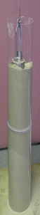
After positioning the sensor, more sand is added to fill the space between it and the borehole casing, holding it firmly in place. The sand should reach within 30mm of the top of the instrument, but should not cover it. This way, the instrument can be more easily recovered when it requires maintenance or replacement. This is particularly important if the borehole is not completely dry, since moist sand does not flow well.
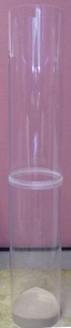
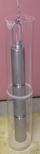
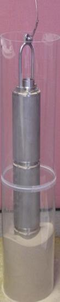
The following photographs show the steps involved in backfilling with sand:
To install a sensor at the bottom of a borehole of known depth using sand backfilling:
Measure or calculate the physical volume of the unit which is to be installed in the borehole. (The volume of a cylinder v = πr2h.) Also measure the internal diameter of the borehole.
Measure and pour in a sufficient quantity of sand to fill the borehole to a depth of around 300mm.
Connect the signal cable to the connector on top of the sensor. Ensure that the “O”-rings inside the housing are clean, and tighten the knurled connector nut to its end stop.
Fix the main lifting cable to the shackle on top of the strain relief mechanism, and run the signal cable through the mechanism using the built-in clamps (without tightening them.) Do not allow the signal cable to bear any of the sensor's weight.
Attach the lifting loop to the sensor using four M5×16 screws (provided).
Join the loop to the bottom of the strain relief mechanism using the linking cable provided.
Hoist up the sensor package and strain relief mechanism until both are hanging by the lifting cable, with the strain relief mechanism extended. Tighten the cable clamps on the strain relief unit, allowing a little slack in the signal cable.
Fix the signal cable to the main lifting cable about 1 m above the strain relief mechanism using a metal clamp (a nylon cable tie may be sufficient for shallow installations.) Leave a little slack in the signal cable between the clamp and the strain relief mechanism.
Position the assembly over the top of the borehole. Do not allow it to drag across the ground.
Lower the sensor so that its base is level with the borehole mouth. Set the depth gauge on the winch to zero.
Calculate how much lifting cable must be lowered into the borehole, taking into account the length of the sensor and the strain relief assembly or digitizer.
Begin lowering the sensor down the borehole, keeping track of the depth reached.
At approximately 20 m intervals, fix the signal cable to the load bearing cable using metal clamps (nylon cable ties every 5 m may be sufficient for shallow installations). This will ensure that the signal cable does not become kinked or trapped within the borehole. Leave a little slack on the signal cable each time, so that it does not bear any weight. Too much slack, however, will cause the cable to scrape against the borehole casing.
Whilst monitoring the depth of the sensor, carefully approach the sand layer at the bottom of the borehole. The lifting cable will go slack when the sensor makes contact with the sand.
If the lifting cable goes slack before the sensor has reached the sand layer, it may have become caught on a bad joint or lip in the borehole; carefully raise and lower the instrument to free it.
When you have reached the bottom, use the winch to lift the package slightly, taking the slack off the cable. This ensures that the sensor is hanging vertically within the borehole, and is no longer in contact with the sand bed.
At this point, you may wish to use an inclinometer monitor unit to check that the instrument is sufficiently close to vertical to be properly centred. See Section 2.4, page 18, for details.
Calculate the volume of dry sand required to fill the gap between the sensor and the borehole liner to the level of the top of the sensor (v = πr2h using the internal radius of the borehole, less the volume of the instrument determined in step 1.)
Pour this sand into the borehole. If you can, check how much of the sensor is covered with sand. Do not overfill the hole.
Carefully slacken the load bearing cable. This will engage the locking arm of the strain relief mechanism and secure the installation within the borehole.
Without pulling or lifting the sensor, lightly shake the cables to remove any sand that may have fallen onto them or onto the strain relief mechanism.
Clamp the load bearing cable to the top of the borehole, and remove the winch.
The sensor can now be centred and unlocked (see Section 3.5, page 39)
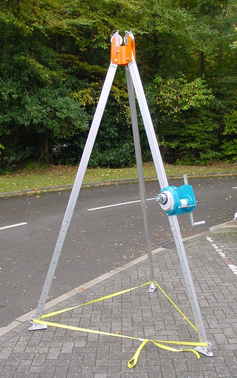
3.3 Assembling the winch
If required, Güralp Systems can provide a winch suitable for installing a borehole sensor. The winch and tripod are supplied as a set of parts which you can assemble on site:
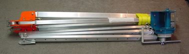
There are two sections for each leg of the tripod. The upper sections are pre-attached to the head of the tripod; the lower sections are supplied detached.
Slide the lower sections all the way into the head with the retaining tape loops facing outwards.
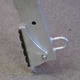
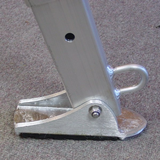
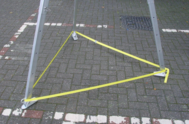
If you are working on a surface of sand or soil, rotate the feet so that the points face downwards (left). For rock or other hard surfaces, ensure the pads face downwards (right).
Erect the tripod above the borehole, and run the yellow retaining tape through the loops. Fasten together the ends of the tape.
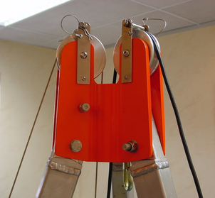
The lifting cable is supplied with a loop at one end. Run this over one of the pulleys at the top of the tripod, so that the loop hangs down between the legs. If the loop is not provided, you can make one by untwisting three outer strands from the (7-core) cable, crossing the two sets, and pleating the three outside strands back around the remaining four in the opposite direction. Secure the loop with a cable clamp.
Run the sensor signal cable through the other pulley. Secure both cables in their pulleys by sliding the attached bolts into place.
Extend each of the three legs in turn to the height you require, finishing at the leg with the winch attached.
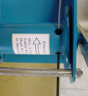
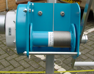
Take the end of the load-bearing cable without the loop, and screw it to the axle inside the winch using a 4 mm Allen key (provided) as shown.
Attach the handle to the side of the winch opposite the ratchet mechanism, and fasten it in place with a collar, washer and screw, using the larger Allen key.
Wind the cable onto the winch by rotating the handle. Ensure that the cable builds up neatly across the drum. Continue winding until the loop on the other end is as high as you need it to install the equipment.
If the ratchet prevents you from winding the cable on, twist the metal boss in the DOWN direction to free the cable.
Remove the handle, and screw it onto the metal spool of the ratchet mechanism.
Hang the strain relief unit and instrument(s) from the loop at the other end of the cable. You are now ready to lower the assembly into the borehole as described above.
3.4 Earthing a borehole sensor
To achieve the best performance from any borehole instrument, you must make sure that the sensor electronics, its casing and the power supply share a common, local ground, and that all power and data lines are adequately protected against lightning and other transients.
This section describes techniques for grounding sensor equipment which have proved effective in many installations. However, local conditions are always paramount, and you should design your installation with these in mind. Any regulations in force at your chosen location must also be followed.
Installations with AC power supplies
If you are using mains (outlet) power, or some other AC power distribution system, we recommend installing a fully isolating transformer between it and the power supply for the instrument. This will allow full control of the local grround.
A spark-gap surge protector should also be installed on the mains side of the transformer, so that transient overvoltages are not transmitted across it. Suitable protectors are available off the shelf from several suppliers. On the sensor side, surge protection is installed as standard within all new Güralp borehole sensors and control equipment. If your surface installation includes third party electronics, digitizers, etc., you may need to install additional protection where power and data lines enter the surface enclosure. Contact Güralp Systems if you are unsure.
Within the installation, a single ground point should be established, which is connected to a local ground plate. All earth lines for equipment in the installation, such as the casings of the transformers and of the sensor electronics, as well as the signal ground line from the sensor, should be connected to this plate.
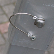
The best local earth point in many installations is the borehole itself. For this to work, the borehole must have a conductive casing and be situated close (<30 m) to the surface installation. In such an installation you need only connect a cable (green wire in the photograph below) from the local ground plate to the borehole casing.
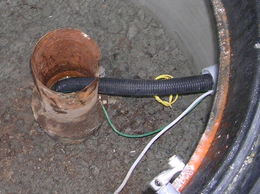
An earth strap can be used to ensure a good connection.
If the lower borehole is filled with salt water, the instrument will be adequately grounded without any further action. Fresh water is an inferior conductor.
In a dry or sand-filled borehole, or one with a non-conducting casing, you will need to ensure the sonde is grounded by some other means. The best option is often to attach the sensor housing to an earth line brought out to the surface and attached to a metal stake driven into the ground nearby.
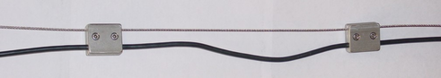
The sensor's load bearing cable is suitable for this purpose, provided it is secured to the sensor's lifting loop with a metallic clamp as shown below. This provides an additional firm contact between the sonde and the load-bearing cable. Installations with downhole digitizers will need similar arrangements at the top and bottom of the digitizer module, or a separate cable for this purpose.
For boreholes with a metallic casing at the bottom and plastic above, we recommend connecting a cable between the sensor housing and the ground plate so that the lower borehole casing acts as the earthing point. Again, the
If there is a significant distance (>30 m) between the borehole and the surface installation, the resistance of the earth cable may make it impractical to use the borehole as an earthing point. In these cases, you will have to connect the local ground plate to an earth stake near to the enclosure; any coupling between this sensor-local earth line and ground lines for other parts of the system must be minimized.
Installations with DC power supplies
Güralp sensors require a 24 V DC power supply. In most cases, this is provided by an isolating DC/DC converter installed at the surface. This converter can be earthed to the local ground plate as above.
However, DC/DC converters contain sensitive electronics, which must be protected thoroughly. We recommend installing a full surge protection unit in addition to the spark gap protector. This protection is installed on the supply side of the isolator, so it must be earthed separately from the borehole installation. Otherwise, transients in the power supply will couple to the sensor.
As with AC installations, if the borehole is more than around 30 m from the surface enclosure, you will need to provide a second earthing point for the local ground plate.
DC power is most commonly available at self-contained installations with power supplied from batteries, solar panels, or a wind generator. In these cases, the power supply may already have protection from transients installed, in which case you may not need such comprehensive protection (although some form of protection is always necessary.)
The surface installation building, and if possible the borehole also, should be protected by lightning conductors. These should lead to ground well away from the borehole. As a rule of thumb, a lightning mast provides a “zone of protection” within a 45 ° cone the height of the mast.
If you are using two earthing points, for example in the DC installation shown above, it may be convenient to connect the lightning conductor to the supply-side earthing point. In any case, the lightning earth must be well separated from the borehole (and its earth, if it needs one.)
3.5 Levelling and centring
Once it is installed, you should level and centre the instrument ready for use. This can be done using the various surface control units.
The 3V and 3ESPV instruments are less susceptible to tilt than instruments with horizontal components. However, to get the best performance you should still make sure the instrument is as close to vertical as possible.
Connect an inclinometer monitor unit to the borehole control unit.
Turn on the borehole control unit using the ON/OFF switch under the transparent flap.
Turn on the inclinometer monitor unit using its ON/OFF switch, and read off the X and Y components of the tilt from the analogue meters.
If both tilts are within the green shaded region, the instrument is close enough to vertical that it can be levelled and centred successfully. If either output is in the red shaded region, move the instrument within the borehole to a place where it can lie closer to vertical.
Connect a handheld control unit (HCU) to the sensor control unit, if you have one.
Unlock the sensor masses, either by pushing the UNLOCK buttons of the borehole control unit, or by holding down the ENABLE and UNLOCK switches of the HCU together for at least six seconds.
When you press the switches, the BUSY LED will come on. After a while, the unlocking process will be completed, and the instrument will start centring itself. Whilst this happens, the BUSY LED will flash.
Monitor the mass position output, either using the HCU or your recording system. The microcontroller inside the unit will zero the output from the sensor. After successful centring, the mass position output should be in the range 0.1 – 0.8 V.
If the centring process leaves the mass position output above ±1.1 V, repeat steps 4 and 5. You will probably need to initiate the centring process several times before the mass is adequately centred.