Chapter 3. Installing the 3ESP Compact
3.1 First encounters
3.1.1 Unpacking
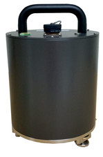
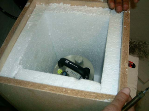
The 3ESP Compact seismometer is delivered in a single transportation case. The packaging is specifically designed for the 3ESP Compact and should be reused whenever you need to transport the sensor. Please note any damage to the packaging when you receive the equipment, and unpack on a safe, clean surface. The package should contain:
|
|
|
|
|
|

If you have ordered the optional break-out box, you will also have received:
|
|
|
|
You will also have received, if ordered, a Hand-held Control Unit (HCU) for monitoring sensor outputs and calibration |
|
Assuming all the parts are present, stand the seismometer in the centre of a bench and identify its external features:
|
|
|
|
| |
|
|
|
|
|
|
|
|
3.1.1.1 Serial number number
The sensor's serial number can be found on the label stuck to the top lid of the sensor. You should quote this serial number if you need assistance from Güralp Systems.
3.1.1.2 Handling notes
The 3ESP Compact is a sensitive instrument, and is easily damaged if mishandled. If you are at all unsure about the handling or installation of the device, you should contact Güralp Systems for assistance.
Avoid bumping or jolting any part of the sensor when handling or unpacking.
Do not kink or walk on the data cable (especially on rough surfaces such as gravel), nor allow it to bear the weight of the sensor.
Do not connect the instrument to power sources except where instructed.
Do not ground any of the signal lines from the sensor.
Avoid moving the instrument whilst the masses are unlocked. The 3ESP Compact is designed to tolerate a certain amount of motion with the sensor masses unlocked, e.g. over short distances carried by hand. For example, if the remote locking procedure fails, removing the instrument for diagnostics is unlikely to damage it. However, you should always lock the sensor masses before shipping or transporting the sensor over longer distances.
3.1.2 Connections
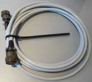
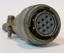
The instrument has a single connector, which can be joined using the cable provided to a digitiser or breakout box. Individually shielded twisted-pair cabling must be used for the sensor outputs, control lines and power supply. If you need to make up a suitable cable, you should confirm the cable type with Güralp Systems.
3.1.2.1 Using a digitiser
The 3ESP Compact can be connected directly to any Güralp Systems digitiser using the signal cable provided. This is the simplest way to use a 3ESP Compact instrument. All the instrument's functions are available through the digitiser, including centring, locking and unlocking.
We recommend that you keep the digitiser near the instrument if at all possible, to minimize the length of analogue cable required. Once digitized, the signal is robust to degradation by noise or attenuation. Keeping the digitiser in the quiet, stable conditions of a seismic installation also provides it with an optimum environment for the on-board ADCs.
3.1.2.2 The breakout box
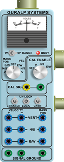
This unit separates the lines in the signal cable, so you can connect a power supply, a recording system, and the hand-held control unit:
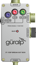
You can also use the breakout box to centre, lock and unlock the sensor masses. You will need to provide power through the breakout box's POWER connector to do this (see below.)
To unlock the sensor masses, hold down the ENABLE and UNLOCK buttons simultaneously for 7 seconds. The BUSY LED will light. All three masses are unlocked, each in turn. The sensor then automatically moves on to centre the masses, during which time the BUSY LED will flash. When the BUSY LED goes out, the instrument is ready for use.
To lock the sensor masses, hold down the ENABLE and LOCK buttons simultaneously for 7 seconds. When the BUSY LED goes out, the instrument is ready for transportation.
To re-centre the sensor masses, hold down the ENABLE and CENTRE buttons simultaneously for 7 seconds. When the BUSY LED stops flashing, the centring process has finished. You may need to initiate several rounds of centring before the instrument is ready; when no more centring is required, pressing the ENABLE and CENTRE buttons has no effect.
For more details on the control system, see section 6.2.
The standard breakout box is rain resistant but not waterproof. If you intend to use a breakout box in your installation, you should site it away from potential flooding. If this is not possible, a larger unit is optionally available which can be immersed in water. (The 3ESP Compact itself is, however, completely waterproof.)
3.1.2.3 Power supply
| or |
|

The sensor requires a 12 Volt DC power supply, which it obtains through the socket and breakout box or digitiser. You will need to make up a suitable cable to connect a 12 V power source to the 10-pin connector on the breakout box (spare 10-pin military specification bayonet connectors are provided for this purpose.) Using a 12 V, 25 Ah sealed heavy-duty lead-acid battery, you should expect the instrument to operate for around a week without recharging.
If you prefer, you can power the 3ESP Compact directly from the connector on the top panel (see Chapter 7.)
The 3ESP Compact draws a nominal current of 75 mA from a 12 V supply when in use. During locking and unlocking of the sensor masses, this current rises briefly to 600 mA. It is recommended that you carry a spare 12 V battery when visiting an installation for maintenance, in case the sensor needs to be moved and the on-site batteries no longer have sufficient charge to perform the locking procedure.
3.1.2.4 Signal output
The sensors output voltages representing ground velocity on floating differential lines. The breakout box provides a RECORDER connector for attaching to a recording system or digitiser. You can use any multi-channel recording system, provided that it has high-impedance floating differential inputs.
If you are using a Güralp Systems digitiser, you can connect the instrument directly to the digitiser without using the breakout box; power will be supplied through the digitiser, which can also activate the sensor control lines.
The breakout box also provides a CONTROL output, which can be connected to the Hand-held Control Unit. This device lets you monitor output signals from the instrument, and perform on-site calibration. For more information, see section 5.2.
3.2 Installation notes
The goal of any seismic installation is to ensure that wave-trains arriving at the instrument accurately reflect the internal motion of subsurface rock formations. To achieve this, the seismometer and its emplacement need to be considered as a mechanical system, which will have its own vibrational modes and resonances. These frequencies should be raised as high as possible so that they do not interfere with true ground motion: ideally, beyond the range of the instrument.
In particular, the sensor needs to be protected against environmental factors such as
fluctuations in temperature,
turbulent air flow around walls or trees, or around sharp corners or edges in the immediate vicinity of the sensor;
vibration caused by equipment in or near the installation, particularly computer equipment; and
vibration caused by heavy machinery (even at a distance), or by overhead power lines.
In seismic vaults, instruments are often installed on piers. It is important to ensure that the interface between the pier and the floor does not introduce noise, and that the pier itself does not have resonant frequencies within the passband. Ideally, a seismic pier will be significantly wider than it is high (to minimize flexing) and will form a single piece with the floor, e.g. by moulding a poured concrete floor with a wooden frame.
Many situations do not allow for the construction of a seismic vault. For example, you may need to deploy quickly to monitor the activity of a volcano showing signs of rejuvenation, or to study the aftershocks of a major earthquake; or the site itself may be too remote to ship in construction equipment.
Temporary installations can be protected against spurious vibrations by
selecting a suitable site,
placing the instrument in a protective enclosure (an open-sided box of 5 cm expanded polystyrene slabs, placed over the instrument and taped down to exclude draughts, makes an excellent thermal shield),
standing the sensor on bedrock where possible, or at least deep in well-compacted subsoil;
clearing the floor of the hole of all loose material; and
using as little extra mass as possible in preparing the chamber.
After installation, the instrument case and mounting surface will slowly return to the local temperature, and settle in their positions. This will take around four hours from the time installation is completed. If you require long-period recording, you should re-zero the instrument after this time.
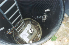
3.3 Installing in vaults
You can install a 3ESP Compact in an existing seismic vault with the following procedure:
Unpack the sensors from their container, saving the shipping boxes for later transportation.
Prepare the mounting surface, which should be smooth and free of cracks. Remove any loose particles or dust, and any pieces of loose surfacing. This ensures good contact between the instrument's feet and the surface.
If it is not already present, inscribe an accurate North-South line on the mounting surface.
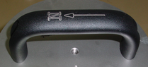
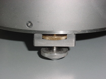
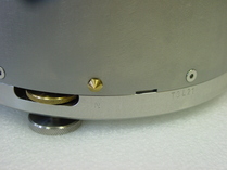
Place the sensor over the scribed line, so that the brass and steel pointers are aligned with the marked directions, with the brass pointer facing North. This can be done by rotating the base of the sensor whilst observing it from above. The brass pointer can be found next to one of the feet.
If you cannot easily see the pointers, you should align the sensor using the north arrow on the handle. However, the alignment of the handle with the sensors inside is less accurate than the metal pointers, so they should be used wherever possible.
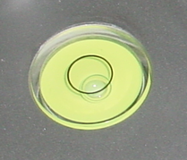
The top panel of the 3ESP Compact includes a spirit level.
Level the sensor using each of the adjustable feet of the instrument in turn, until the bubble in the spirit level lies entirely within the inner circle. (The instrument can operate with up to 2 ° of tilt, but with reduced performance.)
The feet are mounted on screw threads. To adjust the height of a foot, turn the brass locking nut anticlockwise to loosen it, and rotate the foot so that it screws either in or out. When you are happy with the height, tighten the brass locking nut clockwise to secure the foot. When locked, the nut should be at the bottom of its travel for optimal noise performance.
Connect the sensor to a breakout box, or a Güralp digitiser if you are using one.
Connect a 12 V power supply, either directly or through the breakout box or digitiser.
Unlock the sensor. If you have a breakout box or hand-held control unit, you can do this by holding the ENABLE and UNLOCK buttons on the unit down together for 7 seconds. The BUSY LED will start flashing, and then go out.
Alternatively, if you are using a DM24 digitiser and Scream!, right-click on the digitiser's entry in Scream! and select Control…. Click on the Mass control tab, followed by Unlock. (If the Mass control tab is unavailable, make sure the correct sensor type is chosen in the System tab, apply, and open a new Control window.)
Alternatively, if you are using a DM24 digitiser and an EAM, navigate to the Control → Instruments page and click on the Unlock masses icon.
Caution: After unlocking the masses, you should be careful not to move the instrument at all or you may damage it.
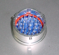
Check the mass position outputs using a digital multimeter, digitiser or the hand-held control units.
Re-centre the masses if required. If you have a breakout box or hand-held control unit, you can do this by holding the ENABLE and CENTRE buttons on the unit down together for 7 seconds. The BUSY LED will start flashing, and then go out
Alternatively, if you are using a DM24 digitiser and Scream!, right-click on the digitiser's entry in Scream! and select Control…. Click on the Mass control tab, followed by Centre. (If the Mass control tab is unavailable, make sure the correct sensor type is chosen in the System tab, apply, and open a new Control window.)
Alternatively, if you are using a DM24 digitiser and an EAM, navigate to the Control → Instruments page and click on the Centre masses button.
Cover the instrument with thermal insulation, for example, a 5 cm expanded polystyrene box. This will shield it from thermal fluctuations and convection currents in the vault. It also helps to stratify the air in the seismometer package. Position the thermal insulation carefully so that it does not touch the sensor package.
Ensure that the sensor cable is loose and that it exits the seismometer enclosure at the base of the instrument. This will prevent vibrations from being inadvertently transmitted along the cable.
3.4 Installing in pits
For outdoor installations, high-quality results can be obtained by constructing a seismic pit.
Depending on the time and resources available, this type of installation can suit all kinds of deployment, from rapid temporary installations to medium-term telemetered stations.
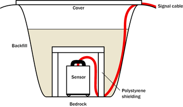
Ideally, the sensor should rest directly on the bedrock for maximum coupling to surface movements. However, if bedrock cannot be reached, good results can be obtained by placing the sensor on a granite pier on a bed of dry sand.
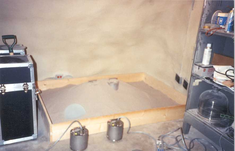
Prepare a hole of 60 – 90 cm depth to compacted subsoil, or down to the bedrock if possible.
On granite or other hard bedrock, use an angle grinder to plane off the bedrock at the pit bottom so that it is flat and level. Stand the instrument directly on the bedrock, and go to step 7.
On soft bedrock or subsoil, you should install a pier as depicted below.
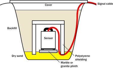
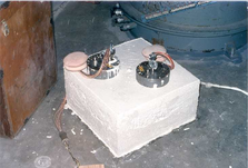
Pour a layer of loose, fine sand into the pit to cover the base. The type of sand used for children's sand-pits is ideal, since the grains are clean, dry and within a small size range. On top of the sand, place a smooth, flat granite plinth around 20 cm across, and shift it to compact the sand and provide a near-level surface.
Placing a granite plinth on a sand layer increases the contact between the ground and the plinth, and improves the performance of the instrument. There is also no need to mix concrete or to wait for it to set, as in step 4.
Alternatively, if time allows and granite is not available, prepare a concrete mix with sand and fine grit, and pour it into the hole. Agitate (“puddle”) it whilst still liquid, to allow it to flow out and form a level surface, then leave to set. Follow on from step 7.
Puddled concrete produces a fine-textured, level floor for emplacing the seismometer. However, once set hard, the concrete does not have the best possible coupling to the subsoil or bedrock, which has some leeway to shift or settle beneath it.
Alternatively, for the most rapid installation, place loose soil over the bottom of the pit, and compact it with a flat stone. Place the seismometer on top of this stone. This method emulates that in step 3, but can be performed on-site with no additional equipment.
Set up the instrument as described in the previous Section.
The instrument must now be shielded from air currents and temperature fluctuations. This is best done by covering it with a thermal shield.
An open-sided box of 5 cm expanded polystyrene slabs is recommended. If using a seismic plinth on sand (from steps 3–4 or 5), ensure that the box is firmly placed in the sand, without touching the plinth at any point. In other installations, tape the box down to the surface to exclude draughts.
Alternatively, if a box is not available, cover the instrument with fine sand up to the top.
The sand insulates the instrument and protects it from thermal fluctuations, as well as minimizing unwanted vibration.
Ensure that the sensor cable is loose and that it exits the seismometer enclosure at the base of the instrument. This will prevent vibrations from being inadvertently transmitted along the cable.
Cover the pit with a wooden lid, and back-fill with fresh turf.
3.4.1 Other installation methods
The recommended installation methods have been extensively tested in a wide range of situations. However, past practice in seismometer installation has varied widely.
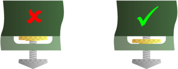
Some installations introduce a layer of ceramic tiles between a rock or concrete plinth and the seismometer (left):
However, noise tests show that this method of installation is significantly inferior to the same concrete plinth with the tiles removed (right). Horizontal sensors show shifting due to moisture trapped between the concrete and tiling, whilst the vertical sensors show pings as the tile settles.
Other installations have been attempted with the instrument encased in plaster of Paris, or some other hard-setting compound (left):
Again, this method produces inferior bonding to the instrument, and moisture becomes trapped between the hard surfaces. We recommend the use of fine dry sand (right) contained in a box if necessary, which can also insulate the instrument against convection currents and temperature changes. Sand has the further advantage of being very easy to install, requiring no preparation.
Finally, many pit installations have a large space around the seismometer, covered with a wooden roof. Large air-filled cavities are susceptible to currents which produce lower-frequency vibrations, and sharp edges and corners can give rise to turbulence. We recommend that a wooden box is placed around the sensor to protect it from these currents. Once in the box, the emplacement may be backfilled with fresh turf to insulate it from vibrations at the surface, or simply roofed as before.
By following these guidelines, you will ensure that your seismic installation is ready to produce the highest quality data.
3.5 Rapid installation
This section details a method of deploying 3ESP Compact instruments with the minimum of additional equipment. This is recommended for situations where seismic instrumentation needs to be installed very quickly, e.g. to study a resumption of volcanic activity, or where difficulty of access to the site prevents you from constructing a full seismic pit. You should always construct a pit if possible, since the data produced will be of significantly higher quality.
Prepare a hole of 60 – 90 cm depth to compacted subsoil, or down to the bedrock if possible.
Clean the hole down to the bottom, and remove any loose material from the mouth. Ensure that the bottom of the hole is relatively flat.
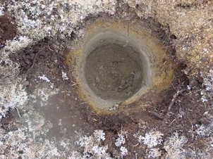
If the bottom of the hole is made of hard rock, you may need to put in some loose sand or soil so that the sensor can be levelled.
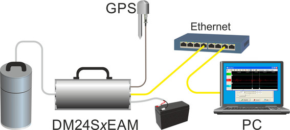
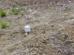
Connect the sensor to cables for the GPS unit and power source.
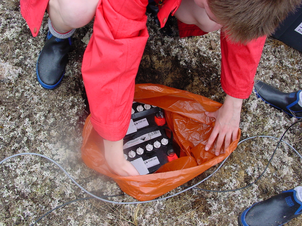
Carefully insert the instrument into the hole, protected by a tough plastic bag to keep water out. Use a bag strong enough to bear the weight of the sensor and breakout box, so that it can be recovered easily.
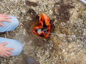
Press the sensor down firmly into the soil, without tapping or hitting it.
Check the bubble level on top of the instrument package.
Adjust the instrument's position if necessary so that the bubble lies entirely within the black circle.
Pack soil or sand around the instrument to hold it steady. Make sure the soil or sand is firmly compacted and not at all loose.
Recheck the bubble level. If you cannot adjust the soil packing at this stage and the sensor is not level, you will need to clear the hole and restart from step 3.
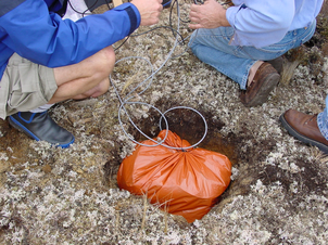
Power the sensor through the breakout box, and unlock the masses by holding down the ENABLE and UNLOCK buttons for seven seconds.
Place the breakout box and any excess cable on top of the sensor, inside the plastic bag.
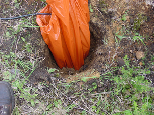
Group the cables coming from the bag for a distance of about 1 m, and keep them together with insulating tape.
Tie the top of the package and fold it over so that water cannot get in. Leave any excess cable within the bag.
Cover the installation with soil or sand until it is no longer visible.
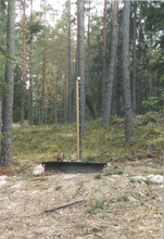
Attach a GPS unit to the cable coming from the sensor. Seal the connection between the data cable and the GPS unit's IEEE 1394 cable inside a plastic bag to protect it from moisture.
Position the GPS unit so that it has a good view of the sky. Bury the cable and connector package so that they cannot be seen.
If possible, place the GPS near the instrument so that it can be found more easily, and the connector package near the GPS so you can retrieve data from the instrument without affecting the installation.
If you are using a battery as a power source, dig a second hole for it. This hole does not need to be as deep as the pit for the instrument—perhaps 10 cm plus the height of the battery.
Attach the sensor power cable to the battery, and wrap it in another plastic bag. Place the bag in the hole.
Tie the bag and fold over, to make the battery as waterproof as possible.
Bury the power cable between the battery and the instrument, and compact soil or sand around the bag.
Fill in and cover the hole so that it is not visible.
3.5.1 Recovery
Care should be taken when recovering the 3ESP Compact, since tapping or banging it can cause damage to the sensors inside. The following instructions assume that you have installed the instrument following the steps above.
Find the GPS receiver, which will be the only feature visible from the surface, and follow the buried data cable from it to the instrument.
Carefully remove earth from the hole until you find the power cable coming from the instrument.
Follow the power cable to the battery pit, and carefully dig away the soil to reveal the battery about 10 cm from the surface.
Disconnect the power cable from the battery. (With the power off, the sensor is less likely to suffer electrical damage during recovery.)
Return to the location of the sensor, and dig down to it. You should be able to remove a spade's head depth of soil without hitting the instrument. Beyond that, using a small hand shovel, follow the wires and carefully remove the remaining soil until you can see the plastic bag. Take special care not to damage the wires, which should be tied together in the vicinity of the bag.
Carry on removing soil, either with your hands or (very carefully!) with the shovel, until the whole bag is uncovered to about half the height of the instrument.
If the hole is relatively dry, open the bag and remove the breakout box and cabling. Power the sensor through the breakout box, and lock the sensor masses by holding down the ENABLE and LOCK buttons for seven seconds. Lift the instrument out by its handle.
Caution: Do not lift the instrument by any of the attached cables. Straining the cables may result in invisible damage, making future installations unreliable.
Alternatively, if the hole is waterlogged, carefully lift out the entire bag in one piece, and remove the contents at the surface. You should lock the sensor masses as soon as you can, and in any case before transporting the instrument.
3.6 Installing in postholes
The 3ESP Compact is suitable for installation in postholes. In soft subsoil, a hole 2 – 4 m deep and 20 cm wide can be conveniently excavated using a tractor-mounted or hand-operated post-hole auger. To minimize surface effects, you should ensure that the hole is at least 1 m deeper than the length of the instrument and, preferably, somewhat more.
Since the hole has no lining, it may occasionally flood. However, most soil types are sufficiently permeable to allow water to soak away, leaving the packing material moist.
To install a 3ESP Compact in a posthole:
Clean the posthole, making sure there is no loose material around the mouth of the hole or on its base.
Prepare the instrument package, making sure the inclinometer is visible, and attach it to a winch or hoist by clamping a light steel cable to the centre of the handle so that the package hangs vertically. Connect the signal cable to the instrument.
Add packing material to the hole to about 15 cm depth. Fine crushed rock, with a high proportion of rock flour and fine particles, makes excellent packing material. Alternatively, a mixture of 3 mm grade angular coarse grit with around 30% medium grit gives good results. Moisten the packing material in the hole and ram firm.
Lower the instrument to the bottom of the hole, but without slackening the lifting cable.
Fill more packing material around the instrument for about 30 cm, moisten, and ram firm.
Use the inclinometer to check that the instrument remains within its tilt tolerance (± 2 °).
Continue filling, moistening and packing until the instrument is buried, checking that the tilt remains within tolerance.
Release the strain on the lifting cable, and allow the packing material to settle for 24 hours.
If all is well after the settling period, release the lifting tackle, coil a tail of the lifting wire into the top of the hole and backfill almost to the surface.
Ensure that the signal cable is slack, and fix it to a support at the top of the hole.
Ram a split wooden bung into the top of the hole, and cover with sandbags.
Attach the signal cable to your recording equipment or breakout box. Power the sensor, and unlock it. Carry out preliminary tests using a hand-held control unit, if required.