Chapter 5. Accessories
5.1 The breakout box
| This unit separates the lines in the signal cable, so you can connect a power supply, a recording system, and the hand-held control unit: |
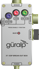
You can also use the breakout box to centre, lock and unlock the sensor masses. You will need to provide power through the breakout box's POWER connector to do this (see below.)
To unlock the sensor masses, hold down the ENABLE and UNLOCK buttons simultaneously for 7 seconds. The BUSY LED will light. All three masses are unlocked, each in turn. The sensor then automatically moves on to centre the masses, during which time the BUSY LED will flash. When the BUSY LED goes out, the instrument is ready for use.
Caution: After unlocking the masses, you should be careful not to move the instrument at all or you may damage it.
To lock the sensor masses, hold down the ENABLE and LOCK buttons simultaneously for seven seconds. When the BUSY LED goes out, the instrument is ready for transportation.
To re-centre the sensor masses, hold down the ENABLE and CENTRE buttons simultaneously for seven seconds. When the BUSY LED stops flashing, the centring process has finished. You may need to initiate several rounds of centring before the instrument is ready; when no more centring is required, pressing the ENABLE and CENTRE buttons has no effect.
For more details on the control system, see section 6.2.
The standard breakout box is rain resistant but not waterproof. If you intend to use a breakout box in your installation, you should site it away from potential flooding. If this is not possible, a larger unit is optionally available which can be immersed in water. (The 3ESPC itself is, however, completely waterproof.)
5.2 The hand-held control unit
| This portable control unit provides easy access to the seismometer's control commands, as well as displaying the output velocity and mass position (i.e. acceleration) on an analogue meter. It takes input from the 26-pin connector at the bottom, and repeats it at the connector on the side for connection to further equipment. The hand-held control unit can be sited up to fifty metres from the breakout box. |
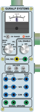
5.2.1 The meter
The meter at the top of the unit allows you to monitor the voltage outputs of the instrument. You can use the knob below to select, for each of the three components, either the mass position output or the velocity output. There is also a RANGE switch allowing you to alter the sensitivity of the meter.
5.2.2 Calibration
The hand-held control unit can be used to calibrate the 3T. To activate the calibration relays, turn the knob to the component you wish to calibrate, and introduce a calibration signal on the CAL SIG banana sockets.
5.2.3 Control commands
You can use the hand-held control unit to centre, lock and unlock the sensor masses.
To unlock the sensor masses, press the ENABLE switch down, and the LOCK/UNLOCK switch up simultaneously. The BUSY LED will light. All three masses are unlocked, each in turn. The sensor then automatically moves on to centre the masses, during which time the BUSY LED will flash. When the BUSY LED goes out, the instrument is ready for use.
Caution: After unlocking the masses, you should be careful not to move the instrument at all, especially if unpowered, or you may damage it.
To lock the sensor masses, press the ENABLE and LOCK/UNLOCK switches down simultaneously. When the BUSY LED goes out, the instrument is ready for transportation.
To re-centre the sensor masses, press the ENABLE and CENTRE switches down simultaneously. When the BUSY LED stops flashing, the centring process has finished. You may need to initiate several rounds of centring before the instrument is ready. When no more centring is required, pressing the ENABLE and CENTRE buttons has no effect.
Note: The ENABLE, LOCK, CENTRE and UNLOCK switches require only a single quick press to initiate the processes. Do not hold them down.
For more details on the control system, see section 6.2.
5.2.4 Outputs
The remaining banana sockets provide easy access to the output voltages of the instrument. For each component (vertical, N/S and E/W):
the left-hand two sockets expose the balanced differential outputs representing ground velocity, and
the right-hand socket exposes the mass position (acceleration) output.
Ground references for each of these voltages are provided at the bottom of the unit. Ensure that you do not connect either side of a differential output to ground.