Chapter 3. Connections, LEDs and Functions
3.1 Connections
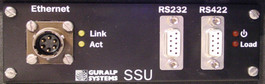
The communications ports are located on the side of the unit.

The RS422 Port is a 9-pin D-type connector for connection over long cables (up to 4000 feet) to a computer equipped with an RS422 interface port. This port will only be active if the server is in local mode. It will be disabled if a connection is made to the RS232 port.
The RS232 port is a 9-pin D-type connector, for connection to a local computer. This port overrides communication via the RS422 port and is active only when the server is in local mode.
The Ethernet port is a 6-pin military specification bayonet plug, which should be connected to your network with a Güralp Ethernet cable. If you want to connect the unit directly to a PC, you will need a “cross-over” or null modem cable, available separately from Güralp Systems. When this port is active, the serial pass-through facility is disabled. However data will be transmitted via the active serial connection.
The other side of the unit has additional communication connections and connections for power.
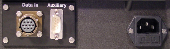
The DATA IN port is a 10-pin military specification bayonet socket, which should be connected directly to the output port of a Guralp digitiser or digital instrument. In addition to data, power for the digitiser and instrument is also carried over this connection.
The Auxiliary Port is a 9-pin D-type connector. It is used to configure the serial server when configuration via the network is not possible. This can also be used as an additional serial server connection if required.
The Mains connection is a standard 3-pin IEC 60320 C14 mains connector. This should be connected to a 110 – 240 Volt AC supply.
3.2 LEDs
The LEDs on the side of the unit, to the right of the two serial ports, display the current power status.
When the unit is not using any power source, neither LED is lit.
The unit will only draw power if the Server Power is set to ON or if an instrument is connected.
When the unit is connected to the mains, the upper LED will be lit.
When a sensor is drawing power from the battery, the lower LED will be lit.
Note: If the battery has too little charge remaining to run the sensor, the upper LED will not light. You should return the unit to mains/outlet power immediately to avoid losing too much data.
Two more LEDs, situated immediately to the right of the Ethernet port, indicate the status of the network interface. These will only be active when the LAN switch is in the ENABLE position.
3.3 Functions
The serial servers' functions can be controlled using switches inside the lid.
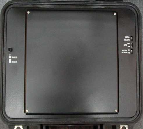
The push button switch on the left hand side selects the serial data format of the DATA In connector. When in the IN position, the data format is RS422 and, when in the OUT position, the format is RS232.
The SERVER POWER switch turns the power to the serial server on and off. If the serial server is left turned off for long periods when stored, this should be in the OFF position to stop the internal battery from being discharged by the server electronics. If mains power is applied, charging of the battery will take place irrespective of the position of this switch. To operate the serial server, this switch should be in the ON position.
The LAN switch enables the network server when in the ON position.
The LOCAL/REMOTE switch controls from where the sensor connected to the DATA IN connector will be controlled. In the LOCAL position, digitiser and sensor control and configuration can be carried out via the RS232 or RS422 ports. In the REMOTE position, control and configuration can be performed across the network.