Chapter 4. Installation
4.1 Connecting over the network
You will need a PC and the Lantronix DeviceInstaller utility to configure the WiPortNR device for your network. The Lantronix DeviceInstaller utility can be downloaded (5 MByte) from the Lantronix web site at
http://www.lantronix.com/products/deviceinstaller/
This program requires the Microsoft .NET framework version 1.1 or later. This library is supplied as standard with some versions of Microsoft Windows but, if it is not present on your system, you can download it from the Microsoft web site, or obtain it through Windows Update.
To install the server:
Connect a 110 – 240 V AC mains (outlet) power supply to the mains connector.
The bottom LED between the serial ports will light, denoting that the unit is running from mains power.
Set the Server Power switch to the ON position.
Note: If the mains power supply is interrupted, the unit will switch to battery power, assuming there is sufficient charge in the battery to drive the network interface. The top LED between the serial ports should light, denoting that the instrument is drawing power from the battery. If there is not, any network connections will be lost. You will need to restore the mains power to recharge the battery.
Set the LAN switch to the ON position.
Set the serial data format for the DATA IN port appropriately for the connected digitiser or device (RS232 or RS422).
Connect the input to the DATA IN port.
Connect the Ethernet port to your network, or directly to a PC using a “cross-over” cable. If you wish, you can connect several units to the same PC using a network hub and configure them all at the same time.
Note: DeviceInstaller will not work through routers or across the Internet. All the devices need to be on the same physical network segment as the PC.
If a DHCP server is running on your network, it may assign the serial server an IP address automatically. If you can find out this address, skip to section 4.1.1.
Start the PC, and run the Lantronix DeviceInstaller utility.
DeviceInstaller's main window has two panels, a tree on the left (with Lantronix Devices at the top) and a table on the right.
The program will automatically look for Lantronix devices on all of your computer's network interfaces. If necessary, you can narrow the selection by clicking on an entry in the tree on the left.
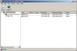
A WiPort-NR entry should appear in the table on the right, denoting that a device has been detected. If more than one WiPort entry appears, DeviceInstaller has detected several devices.
For every detected device, the program shows the Hardware Address (i.e. the MAC address), and the IP address it is currently using. If your local network uses a DHCP server, the device will ask the DHCP server to assign it an address. Otherwise, a random address will be chosen automatically.
Automatic random addresses all begin with 169.254. The unit will choose a different one every time it is power-cycled or rebooted.
The address of the unit may be shown in red with the status Unreachable. If this happens, the unit and PC cannot communicate because they are not on the same subnet. You will need to change the address of one or the other before they will be able to communicate.
Click Assign IP (
 ) to start the IP configuration wizard.
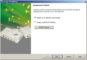
Follow the instructions in the wizard to set the IP address, or configure DHCP if you are using a DHCP server.
Once set, click Search (
 ) to find the sensor with its new address.
If you want to configure the unit to use a static IP address, use the Assign IP wizard as above, and click Search again.
Double-click on the entry which corresponds to the unit you want to configure.
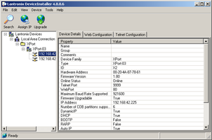
The right-hand panel will change to show the current properties of the device.
Switch to the “Web Configuration” tab and click Go (
 ) to open the Web configuration interface.
Alternatively, click Use External Browser (
 ) to use your own Web browser to configure the instrument.
In either case, unless you have previously configured password protection, simply click
 if prompted for a user name and password.
Follow the steps in section 4.1.2 to configure the module using its Web interface.
4.1.1 Using DHCP
If you cannot install DeviceInstaller on your PC, or you do not wish to, you can also get access to the unit using a standard DHCP server. In most cases you will need to have administrative privileges to do this.
Install and start the DHCP service on your PC.
Connect the unit's ETHERNET port to the the PC's network interface, either using a crossover Ethernet cable or through a network hub.
If you wish, you can connect several units to the same PC using a network hub and configure them all at the same time.
Note: DeviceInstaller will not work through routers or across the Internet. All the devices need to be on the same physical network segment as the PC.
Query the DHCP server to find out what IP addres it gives to each instrument.
To configure a device, enter its IP address into a web browser. Unless you have previously configured password protection, simply click
if prompted for a username and password.
4.1.2 Configuration with the Web interface
Once you have access to the WiPort-NR's Web interface, you can configure it with its proper settings. Unless you have previously configured password protection, simply click
if prompted for a user name and password.The Web page is divided into three. A menu on the left switches between pages of configuration options on the right. There is also a banner at the top, which tells you the current firmware revision and the MAC address.
To navigate around the Web interface, click on the entries in the left-hand menu. If you make changes to the settings on any page, save them by clicking
before you leave the page. The changes to the settings do not take place at this stage: a subsequent step is needed to apply the changes.The WiPort-NR has two serial channels to which you can connect. By default, these are exposed on TCP ports 10,001 and 10,002.
Channel 1 (normally port 10,001) is connected to a serial console which is exposed on the auxiliary port connector. If you have problems connecting to the unit over a network, you can attach a serial cable to this port and use Scream! to access the console. Plaese contact GSL technical support if you need to use this feature.
Channel 2 (normally port 10,002) is connected to the unit's DATA IN input.
Click on Channel 2 – Serial Settings.
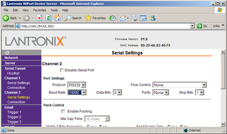
Set the Baud Rate to match the line speed of the digital output of the connected digitiser.
Note: If you change the baud rate in Scream! or using the terminal, you must come back to this page and change the Baud Rate setting.
The remaining settings can be left at their default values. Click
to save your changes.For full information on the WiPort-NR's configuration options, please refer to the WiPort documentation, which is available on the Lantronix Web site, http://www.lantronix.com/.
When you have finished setting up the WiPort-NR, apply the new settings by clicking
 . The WiPort-NR will re-boot with the new settings in effect.
Note: Simply changing settings in the web page and clicking
does not effect any functional change. You must click before the changes take effect.If the WiPort-NR is using an automatically chosen random IP (beginning with 169.254), the IP address will change when you do this. You will need to go back to DeviceInstaller to find out the new IP address.
4.1.3 Configuring Scream to receive data over the network
If the connected device is a GSL digitiser or digital instrument, such as a 6TD, you can now configure Scream to receive data over the network.
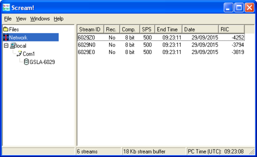
Run Scream!, and choose Windows → Network Control from the main window to open the Network Control window.
Switch to the My Client tab, and right-click in the server list below.
Ensure that the “Receive UDP Data” checkbox is ticked.
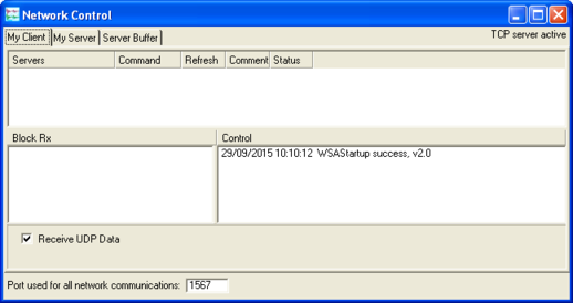
Right-click in the upper pane (the “Servers” list) and choose “Add TCP Server…”
Enter the IP address and port number on which the server is waiting for requests, separated by a colon : (e.g. 192.168.42.98:10002). If you have not altered it in the server's configuration, the port number will be 10002.
Test communications by right-clicking on the newly-added server entry, and selecting Connect. If communication is good, the contents of the Status column will change to Connected.
Check that data streams appear in Scream!'s main window.
To disconnect from the server, right-click on its entry and select Disconnect. Scream! automatically disconnects from all connected servers when it exits.
Note: If the server loses power, either because the battery has run down or because the panel switch on the unit is flipped to Serial, the data connection will be lost. You will need to Disconnect Scream! from the server, and then Connect once more to start receiving data.
4.2 Connecting over a serial link
Set the Serial Server switch to the “Local” position.
Connect a 110 – 240 V AC mains (outlet) power supply to the mains connector.
The bottom LED to the right of the serial ports will light, denoting that the unit is running from mains power.
Connect your instrument to the DATA IN port.
Connect the RS232 port to your PC or other serial device.
Start the PC, and run Scream!. Configure the serial port. The RS232 port is a direct, pin-to-pin connection to the DATA IN port, so the Baud rate and other settings depend on the digitiser's configuration.
Check that data streams appear in Scream!'s main window.