Chapter 3. Setting up the GPT
Open the lid of the Pelicase® and, using an appropriate driver, remove the Torx screws securing the top cover.
Carefully remove the top cover to gain access to the main PCB.
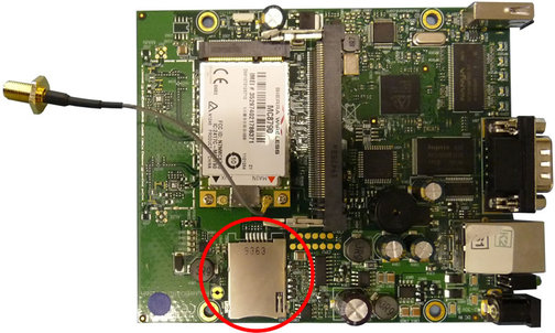
Insert the SIM card into the housing on the PCB, as shown below:
Re-assemble the device by locating and securing the top cover.
Connect a standard serial cable between the nine-pin D-connector and a PC. See Appendix A on page 12 for connector pin-outs.
Note: A “null modem” serial cable must be used to connect the device to a PC.
Open a terminal connection as described in Appendix B on page 15.
Use the power cable to connect the 4-pin Power connector to a fused DC power source providing any voltage between 10 V and 28 V. Wait a few seconds for the system to boot.
The device is now live and ready for configuration and testing, as described in section 4.