Chapter 6. Appendices
6.1 Appendix A - Connector pin-outs
6.1.1 Power
This is a standard 4-pin “mil-spec” plug, conforming to MIL-DTL-26482 (formerly MIL-C-26482). A typical part-number is 02E-08-04P although the initial “02E” varies with manufacturer. Suitable mating connectors have part-numbers like ***-08-04S and are available from Amphenol, ITT Cannon and other manufacturers. |
|
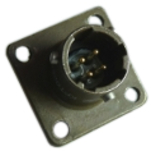
Pin | Function |
A | Ground |
B | Power input +10 to +36VDC |
C | Not connected |
D | Not connected |
| Wiring details for the compatible socket, ***-08-04S, as seen from the cable end (i.e. during assembly). |

6.1.2 Network
This is a standard 6-pin “mil-spec” plug, conforming to MIL-DTL-26482 (formerly MIL-C-26482). A typical part-number is 02E-10-06P although the initial “02E” varies with manufacturer. Suitable mating connectors have part-numbers like ***-10-06S and are available from Amphenol, ITT Cannon and other manufacturers. |
|
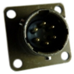
Pin | Function |
A | Not connected |
B | Data transmit +ve (RJ45 pin 1) |
C | Data receive +ve (RJ45 pin 3) |
D | Not connected |
E | Data receive –ve (RJ45 pin 6) |
F | Data transmit –ve (RJ45 pin 2) |
| Wiring details for the compatible socket, ***-10-06S, as seen from the cable end (i.e. during assembly). |

6.1.3 Serial console
These are standard DE9M (TIA-574) sub-miniature (D-sub) plugs, conforming to DIN 41652 and MIL-DTL-24308. They are very widely available, as are suitable mating connectors. A standard “null modem” cable should be used when connecting to a PC. |
|
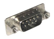
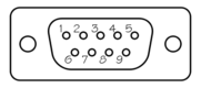
Pin | Function |
1 | Not connected |
2 | RS232 transmitted data* |
3 | RS232 received data* |
4 | Not connected |
5 | Ground |
6 | Not connected |
7 | Not connected |
8 | Not connected |
9 | Not connected |
| Wiring details for the compatible socket, DE9F, as seen from the cable end (i.e. when assembling). |
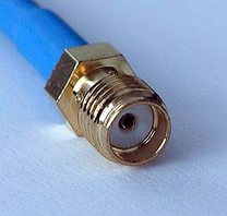
6.1.4 Antenna
This is a standard female SMA connector conforming to Military specification sheet MIL-C-39012. They are very widely available, as are suitable mating connectors. |
|
6.2 Appendix B - Using terminal emulators
There are a number of terminal emulator programs that you can use to access the serial ports of the modem. Güralp recommend the use of PuTTY on Windows PCs and picocom on Linux PCs. These are detailed below.
6.2.1 Using PuTTY.
PuTTY is a free terminal emulation and ssh package for windows. It can be downloaded from www.chiark.greenend.org.uk in a number of different packages. The easiest package to use is the 'windows installer'. Install PuTTY by following the simple on-screen instructions.
Start PuTTY by clicking on the desktop icon or Start-menu entry
Click on Serial at the bottom of the category menu on the left:
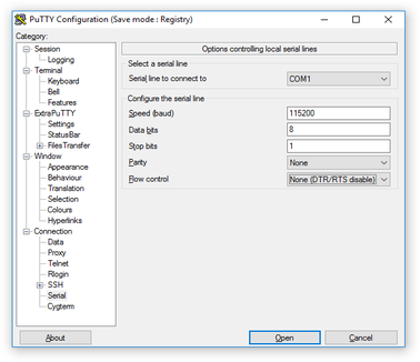
Select a serial line to connect to. This is usually COM1.
Configure the serial line with the following settings:
Speed (baud): 115200
Data bits: 8
Stop bits: 1
Parity: None
Flow control: None (DTR/RTS disable)
Click on Session in the main menu on the left.
In the right hand part of the window, use the radio buttons to select the Serial Connection type. Check the Serial line and Speed fields are correct:
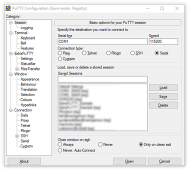
To save the settings, enter a suitable session name in the Saved Sessions field and then click
 .
.Note: The next time you start PuTTY, your saved session will appear in the list and you can simply double-click it to open a new session with the same settings.
Click the
 button to start the terminal emulator.
6.2.2 Using picocom for linux
Picocom is a simple terminal emulation program for linux. More information on picocom is available at http://linux.die.net/man/8/picocom
Ensure picocom is installed. Under Debian orUbuntu, you can type sudo apt-get install picocom to install it if required.
Run picocom /dev/ttyS0 -b 115200 (where /dev/ttyS0 is the serial port device and 115200 is the baud rate).
When you have finished your session, type
 +
+ then
then  +
+ to quit.
6.3 Appendix C – Configuration reset
It is possible to restore all configuration parameters of the GPT (including the administration password) to their factory default settings.
Caution: ESD: The circuit board within the GPT includes components which can be damaged by electrostatic discharge. Always work on a properly grounded dissipative surface and wear a suitable grounded wristband. Ground yourself by touching an earthed conductor before handling the circuit board.
Open the lid of the Pelicase® and, using an appropriate driver, remove the Torx screws securing the top cover.
Carefully remove the top cover to gain access to the main PCB.
Identify the two kidney-shaped pads shown in the pictures below:
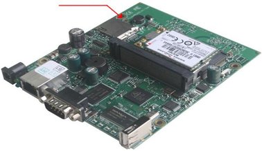
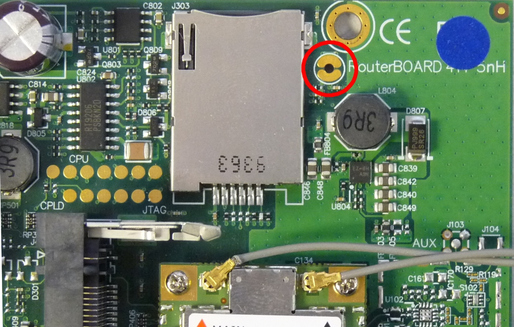
Using a metallic object, such as a screwdriver, short the two kidney-shaped pads together.
With the pads still connected together, power up the GPT. Keep the short in place until the USER LED starts flashing and then release it.
Note: If you keep the short in place until the LED has stopped flashing, the unit will attempt to reinstall the firmware from the Internet. If you suspect that this has happened, simply power-cycle the unit and start this procedure again.
Re-assemble the device by locating and securing the top cover.
Note that all configuration changes that you have made will be lost and the unit will need re-configuring.
6.4 Appendix D - Specifications
Parameter | Specification |
Air Interface | HSUPA, HSDPA, EDGE, GPRS |
Approvals | FCC, IC, CE, GCF, PTCRB, A-Tick, AT&T, Telstra, NTT DoCoMo, Softbank, Bell |
Operational Temperature | -25°C to +60°C |
Case size | 23.2 x 19.2 x 11.1 cm |
Weight | 1.2kg |
Power supply | 10 - 28 VDC |
Power consumption | 3.6W |
6.5 Appendix E - Revision history
2011-08-22 | A | New document |
2012-10-04 | B | Tidy-up and re-write |
2012-10-22 | C | Added reset instructions, gdi-link usage details and simplified set-up |
2012-10-23 | D | Minor corrections |
2015-07-24 | E | Added ESD warnings |
2017-07-10 | F | Modified to support MC8705 modem |