Chapter 3. Installation
Warning: The I/O Expander Module is capable of switching lethal voltages but the exposed connectors will then present a significant risk of injury or death. It is essential to provide a suitable secondary enclosure in such applications.
Caution: The I/O Expander Module is supplied in a UL94-rated ABS enclosure. It is not suitable for use outdoors or in environments where it could be exposed to excessive temperature, humidity, dust or hazardous chemicals. It is essential to provide a suitable secondary enclosure in such applications.
3.1 Connection to Minimus
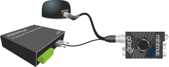
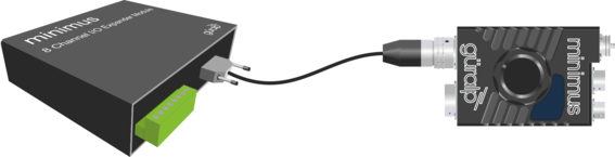
The DE9f connector of the I/O Expander Module, labelled SERIAL PORT, connects to the Minimus’ Analogue port. It can be connected in two ways.
If an analogue sensor, such as a Güralp Fortis, is to be used in conjunction with the Minimus, a ‘Y’-cable, part number CAS-MIN-0007, is used to connect the I/O Expander Module:
If no analogue sensor connection is required, a simple point-to-point (non-'Y') cable, part number CAS-MIN-0006, should be used:
In either case, a digital sensor (or string of digital sensors) can be connected to the Minimus in the normal way, if required.
3.2 Connection to external equipment
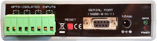
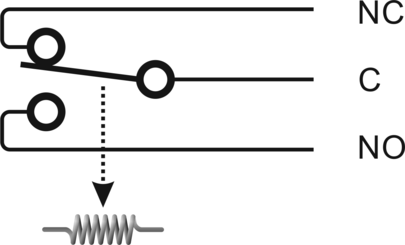
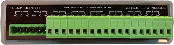
The I/O Expander Module provides eight relay outputs for connection to external equipment. Each relay output is single-pole, double-throw. The contacts are labelled as follows:
The common contact is labelled ‘C’
The normally-open contact is labelled ‘NO’
The normally-closed contact is labelled ‘NC’
The contact arrangement and associated labelling is illustrated in the following diagram:
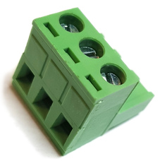
Each set of relay contacts is provided with a separate, detachable, three-pole terminal block.
The terminal block can be removed from the I/O Expander Module by pulling directly outwards with moderate force. In the illustration above, the first two blocks have been removed.
Caution: Do not wiggle, twist or bend the connector when attempting to remove it. This may damage the unit.
Once each terminal block is removed, the associated wiring to the external equipment can be connected to it. Each terminal block has three wiring receptacles, which accept wires in the range 24 AWG to 12 AWG.
For each wire, strip back 4 mm of insulation, as shown below. If using stranded wire, strip around 6 mm, twist the loose strands together and then crop the twisted ends to 4 mm.
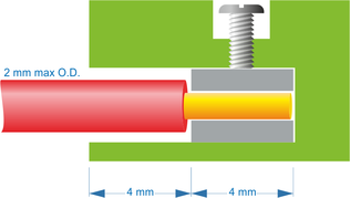
Insert the prepared wire fully into the contact block and fully tighten the screw using a 3 mm flat-headed screw-driver. Check that no loose strands protrude.
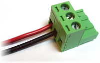
Check that the connection is sound by tugging sharply on the cable; it should be impossible to dislodge with moderate force. Repeat for all required connections. Unused terminals can be ignored.
The terminal block(s) can then be re-inserted into the I/O Expander Module. A positive click should be felt as they are fully inserted.
3.3 (Optional) Connection to power supply
The I/O Expander Module does not require an external power supply when connected to the Minimus.
When used with equipment other than the Minimus, the I/O Expander Module requires an external regulated 12 V DC power supply, rated at 500 mA or more.