Chapter 4. Typical output connections
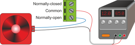
4.1 Example: 12 V DC alarm
Provided that the alarm presents a resistive load and draws less than 5 Amps, it can be connected to a power supply with the common and normally-open contacts in series with the positive supply line. The alarm will sound when the relay is activated.
4.2 Example: 240 V AC indicator lamps
The two lamps presents resistive loads so they can be connected directly but, in this case, the voltages involved are sufficient to present a risk to life. The I/O Expander Module and its associated wiring must, therefore, be installed inside a grounded metal enclosure.

Warning: The installation must be carried out by a qualified electrician in accordance with all applicable regulations and legislation.
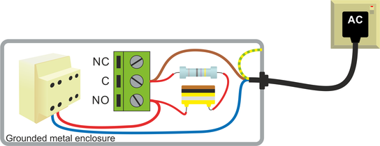
4.3 Example: 240 V AC contactor
Contactors typically present an inductive load, which can cause arcing between the relay contacts. This, in turn, can lead to premature failure of the I/O Expander Module.
This can be mitigated by installing a 47 Ω, ½ W resistor in series with a 100 nF, 400 V non-polarised capacitor (values suitable for 240 V AC applications) connected in parallel with the switch contacts.
Again, the voltages involved are sufficient to present a risk to life. The I/O Expander Module and its associated wiring must, therefore, be installed inside a grounded metal enclosure.
Warning: The installation must be carried out by a qualified electrician in accordance with all applicable regulations and legislation.