Chapter 3. Operation
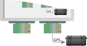
The CMG-RTM has two 10-pin bayonet connectors: one, on the right, for attachment to a power supply (during synchronisation) or to a digitiser (during operation) and one, on the left, for attachment to a GPS receiver.
If the unit has been disconnected from power for some time, the internal battery will be discharged. The unit automatically shuts down under these circumstances.
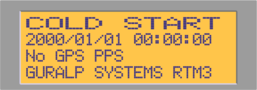
The unit should first be connected to either a digitiser or power supply, using the right-hand connector. The following screen will be displayed:
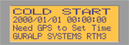
The second line shows the date and time, according to the internal clock. The third line shows that no GPS data are currently being received.
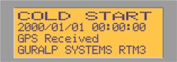
A GPS receiver should then be attached to the left-hand connector.
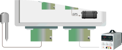
The third line of the display will change to show that GPS signals are being received.
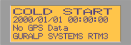
The GPS receiver produces two sets of outputs: a stream of textual data know as the NMEA (because it is in NMEA 0183v1.5 format) and a one-Hertz pulse train known as the PPS. The NMEA provides coarse timing (to the nearest second) and the PPS provides accurate sub-second timing.
Both signals are required for correct operation. If either is missing, there is a problem with the receiver, the cable or the CMG-RTM itself.
If the NMEA is missing, the following screen is displayed:
If the PPS is missing, the following screen is displayed:
If you see either of these screens, please check the GPS cable and connections. If no fault is apparent, please contact GSL technical support for advice.
While the GPS receiver is looking for satellite signals, the display will change:
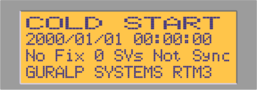
In the illustration above, the receiver does not know where it is (No Fix) and it can see no satellites (SVs stands for “Space Vehicles”, which is standard GPS terminology for the satellites used by the GPS system). As a result, the system is not synchronised (Not Sync).
Over the next minute or so, the receiver will start to receive data from more satellites. It will first calculate an automatic two-dimensional fix (A2D). This is not sufficient for synchronisation purposes and if this condition persists, the receiver should be moved to obtain a better view of the sky. For more information about the GPS system and optimum receiver placement, please see our GPS installation guide at http://www.guralp.com/howtos/setting-up-gps-equipment.shtml.
When sufficient satellites have been in view for enough time, the GPS receiver will establish a full three-dimensional fix (A3D) and the display will change to the following:
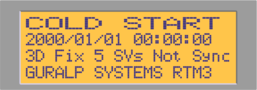
Here, five satellites are in view (5 Svs).
After a minute or so with a stable three-dimensional fix, the clock control system will start the synchronisation process and the display will change to the following:
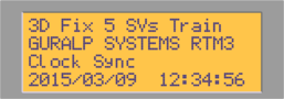
The internal clock will be coarsely adjusted until it is in line with the GPS time, and then the offset (the difference between internal clock time and GPS time) and drift (the first derivative of the offset) are monitored while the pulse width modulation value is altered to minimise both. This process is known as training.
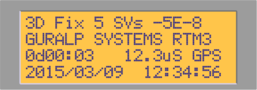
In the display above, the first line gives the drift, or frequency error (-5E-8) as -5×10⁻⁸. Note that the drift value is unit-less, representing seconds per second. The third line shows the elapsed time since synchronisation (0d00:03), which is zero days, zero hours and three minutes, and the current offset from PPS, which is 12.3µs. The last line shows the date and time.
The CMG-RTM should now be left until both offset and drift reach sensibly small values. In a thermally stable environment with good satellite visibility, this process should take less than an hour.
The GPS receiver and power supply (or digitiser) can then be disconnected. The display will change to show that GPS data are no longer being received:
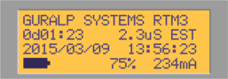
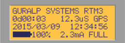
The second line shows the elapsed time since synchronisation (0d01:23) and the offset from GPS time, which is now an estimate (EST). The bottom line shows the state of charge of the internal battery. If the battery were fully charged, the display would look like this:
The unit can now be completely disconnected from external power. It enters a low-power sleep mode, turns off the display back-light and stops transmitting GPS signals.
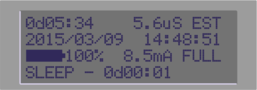
The display shows the time since synchronisation and the estimated offset from GPS time; the date and time from the internal clock; the battery status; the sleep indicator and the time during which it has been sleeping. If the battery is fully charged, the unit will run for approximately eight days in this mode.
The unit is now free-running under battery power and can be transported to the deployment site, where the target digitiser should be plugged into the right-hand connector, which will then provide power. The CMG-RTM will provide accurate timing to the digitiser.