Chapter 3. Installation Guide
3.1 Unpacking
Remove all parts from their packaging, taking care to hold the display unit by the edges only so as not to apply any force to the screen area.
Please check that you have received all of the necessary parts. Your kit should contain:
The Strong Motion Display system;
DC power adaptor;
Mains lead (line cord) for DC power adaptor;
Keyboard/Mouse adaptor;
A380 Single Board Computer User Guide (printed);
S-series Panel PC User Guide (printed);
S-series Panel PC User Manual (on CD);
Two unconnected four-pin male military-specification bayonet connectors; and
Two unconnected four-pin female military-specification bayonet connectors.
Inspect each part carefully before use.
Warning: Do not apply power to the system if any of the electrical parts have been damaged during transit. Contact Güralp support for assistance if in any doubt.
3.2 Mechanical Installation
The Strong Motion Display is intended to be wall-mounted and is fitted with an integral mounting bracket for this purpose.
Warning: The unit weighs 5.7kg and this should be born in mind when assessing the suitability of a possible location and the fixings to be used.
The Strong Motion Display is mounted using four screws. The screws are fixed to the wall, tight to within 2mm, and the unit is then hung from the screw-heads via key-hole slots in the mounting bracket. Fixing plugs appropriate to the type of wall construction should be used and 30mm clearance should be allowed around all sides of the unit in order to provide ventilation.
The screw-holes should be drilled as in the following diagram:
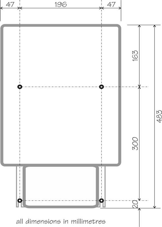
Once the unit is mounted, the lower screws can be fully tightened.
3.3 Electrical Installation
The Strong Motion Display requires the following connections:
 100VAC - 240VAC, 50/60 Hz mains (line) power via an IEC C13 line socket to the supplied DC power adaptor. A suitable cable is included, terminated with a BS1363 (standard UK mains) plug, but any suitable cable can be substituted;
12V DC power from the integral lead of the power adapter to the power input socket on the Strong Motion Display;
RS232 serial data from a CMG-DM24 digitiser or CMG-5TD digital sensor.
The DC power and RS232 data connectors are located on the right-hand side of the unit and are depicted in Section 5.1.1..
Note: The power switch on the right-hand side of the unit should not be used. The Strong Motion Display should be powered up and down by either by switching mains (line) power or by connecting and disconnecting the 12V DC power lead.
During initial set-up, the following connections are required:
The supplied keyboard/mouse “Y“ adapter cable should be connected to the six-pin mini-DIN keyboard/mouse socket on the side of the Strong Motion Display.
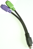 A standard PC keyboard with a PS2-compatible mini-DIN connector should be connected to the purple socket on the “Y” adaptor cable.
A standard PC mouse with a PS2-compatible mini-DIN connector should be connected to the green socket on the “Y” adaptor cable.
The keyboard/mouse connector is located on the right hand side of the unit and is depicted in Section 5.1.1.
In addition to the above, optional connections can be made to the following:
two connectors wired internally to normally-open relay contacts which are activated when the user-programmed thresholds are exceeded; and
two connectors to providing analogue (current driver) outputs.
These connectors are located on the bottom face of the unit and are shown in Section 5.1.1.