Chapter 5. Appendices
5.1 Connector locations
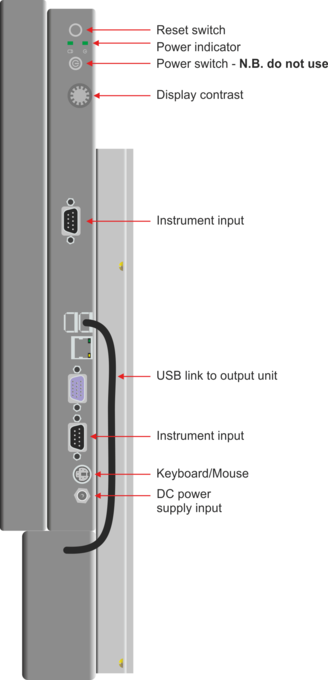
5.1.1 Input connections
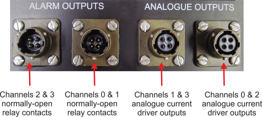
5.1.2 Output connections
The output connections are located on the bottom face of the unit. The pin-outs are described in Section 5.2. Mating connectors are provided to allow you to connect your own equipment.
5.2 Connector pin-outs
5.2.1 Alarm (relay) outputs
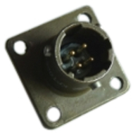
These are standard 4-pin military-specification bayonet plugs, conforming to MIL-DTL-26482 (formerly MIL-C-26482). A typical part-number is 02E-08-04P although the initial “02E” varies with manufacturer. Suitable mating connectors are provided and have part-numbers like ***-08-04S. They are also available from Amphenol, ITT Cannon and other manufacturers. |
|
5.2.1.1 Alarm output (inner connector)
Pin | Function |
A | GUI Digital output 0 - normally open relay contact to pin D |
B | GUI Digital output 1 - normally open relay contact to pin C |
C | GUI Digital output 1 - normally open relay contact to pin B |
D | GUI Digital output 0 - normally open relay contact to pin A |
5.2.1.2 Alarm output (outer connector)
Pin | Function |
A | GUI Digital output 2 - normally open relay contact to pin D |
B | GUI Digital output 3 - normally open relay contact to pin C |
C | GUI Digital output 3 - normally open relay contact to pin B |
D | GUI Digital output 2 - normally open relay contact to pin A |
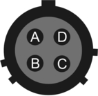
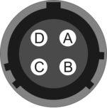
| Wiring details for the compatible socket, ***-08-04S, as seen from the cable end. |
5.2.2 Analogue outputs
These are standard 4-pin military-specification bayonet sockets, conforming to MIL-DTL-26482 (formerly MIL-C-26482). A typical part-number is 02E-08-04S although the initial “02E” varies with manufacturer. Suitable mating connectors are provided and have part-numbers like ***-08-04P. They are also available from Amphenol, ITT Cannon and other manufacturers. |
|
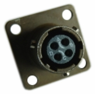
5.2.2.1 Analogue output (outer connector)
Pin | Function |
A | GUI analogue output 0 ground |
B | GUI analogue output 2 ground |
C | GUI analogue output 0 positive |
D | GUI analogue output 2 positive |
5.2.2.2 Analogue output (inner connector)
Pin | Function |
A | GUI analogue output 1 ground |
B | GUI analogue output 3 ground |
C | GUI analogue output 1 positive |
D | GUI analogue output 3 positive |
| Wiring details for the compatible plug, ***-08-04P, as seen from the cable end. |
5.2.3 Digitiser ports
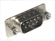
These are standard DE9M (TIA-574) sub-miniature (D-sub) plugs, conforming to DIN 41652 and MIL-DTL-24308. They are very widely available, as are suitable mating connectors. |
|
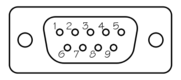
Note: The pin-out is the same as a standard COM port with DTE wiring.
Pin | Function |
1 | Carrier detect (unused) |
2 | RS232 receive data |
3 | RS232 transmit data |
4 | Data terminal ready (unused) |
5 | Ground |
6 | Data set ready (unused) |
7 | Request to send (unused) |
8 | Clear to send (unused) |
9 | Ring indicator (unused) |
| Wiring details for the compatible socket, DE9F, as seen from the cable end. |
5.3 Specifications
Parameter | Value |
Physical | |
Height (excluding connectors) | 483 mm (19”) |
Width | 290 mm (11.4”) |
Depth | 80 mm (3.2”) |
Weight | 4.6 kg (10lb 2oz) |
Electrical | |
DC Power Supply Adaptor | |
Input voltage | 100 V AC - 250 V AC |
Input frequency | 50 - 60 Hz |
Input current (max) | 2.5 A |
Output voltage | 12 V DC |
Output current (max) | 6.6 A |
Display Unit | |
Input voltage | 12 V DC |
Alarm Outputs - relay | |
Maximum AC rating | 8 A @ 250 V AC |
Maximum DC rating | 5 A @ 30 V DC |
Alarm Outputs - analogue | |
Voltage | 30 V DC |
Current | |
Minimum (zero reading) | 4 mA |
Maximum (F.S.D.) | 20 mA |