Chapter 3. First Encounters
3.1 Handling notes
Although the 6T has a rugged design, it is still a sensitive instrument, and can be damaged if mishandled. If you are at all unsure about the handling or installation of the sensor, you should contact Güralp Systems for assistance.
Avoid bumping or jolting the seismometer when handling or unpacking.
Do not kink or walk on the data cable (especially on rough surfaces such as gravel), nor allow it to bear the weight of the sensor.
Do not connect the instrument to power sources except where instructed.
Do not ground any of the signal lines from the sensor.
All parts of the 6T are waterproof to IP68 - the instrument can withstand prolonged immersion under 3 m of water for 72 hours.
3.2 Unpacking
The 6T seismometer is delivered in a single transportation case. The packaging is specifically designed for the 6T and should be reused whenever you need to transport the sensor. Please note any damage to the packaging when you receive the equipment, and unpack on a safe, clean surface. For each instrument in the packaging, you should have received:
the seismometer;
the breakout box (which provides separate connections for the signal, control and power lines);
a data cable, for connecting the instrument to a Güralp digitiser, such as the Güralp DM24;
a calibration and installation sheet.
Assuming all the parts are present, stand the seismometer in the centre of a bench and identify its external features:
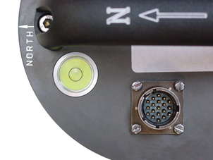
a handle with North indication,
a 26-way bayonet plug for data and power;
a pressure-release cap;
a cover-plate for the output offset adjustment potentiometers;
a spirit level,
three feet (two adjustable, and one fixed), and
two accurate orientation pins (one brass and one steel).
3.2.1 Serial number
The sensor's serial number can be found on the label affixed to the side of the instrument. You should quote this serial number if you ever need assistance from Güralp Systems.
3.3 Connection
The instrument is supplied with a 26-way cable with military-specification bayonet connectors on each end; this carries both power and output signals and is suitable for connecting directly to a Güralp digitizer.
An optional breakout box, if ordered, provides individual signal and power connectors, or you can make up your own cable if you prefer.
3.3.1 The breakout box
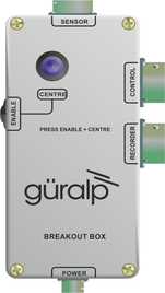 If you are using the optional Güralp breakout box, the data cable from the instrument should be attached to its SENSOR connector. Connectors are also provided at the CONTROL and RECORDER outputs, for attaching to an optional hand-held control unit or a Güralp digitizer.
The breakout box also provides a standard Güralp power connector on a 10-pin military-specification bayonet plug. The 6T draws a nominal current of 38 mA from a 12 V supply when in use; thus, using a 12V, 25 Ah sealed heavy-duty lead-acid battery, you should expect the instrument to operate for around a week without recharging.
The CENTRE button switches the instrument into one-second mode whilst it is pressed. This mode allows you to monitor the mass positions whilst you adjust the offsets manually. If you prefer, you can use the equivalent switch on a Hand-held Control Unit (see below.)
3.3.2 The hand-held control unit (HCU)
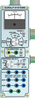 This portable control unit provides easy access to the seismometer's control commands, as well as displaying the output velocity and mass position (i.e. acceleration) on an analogue meter.
The upper section of the HCU contains a simple voltmeter for monitoring various signals from the instrument.
To monitor the velocity outputs, switch the dial to V, N/S or E/W LOW VEL according to the component you want to monitor.
To monitor the mass position outputs, switch the dial to V, N/S or E/W MASS POS. Whilst you are adjusting mass position offsets, you should also switch the instrument out of broadband mode by switching the rightmost CENTRING SELECT switch to 1 SEC VEL, or by holding down the CENTRE button on a breakout box.
You can set the range of the meter with the RANGE switch. When switched to 10 V, the meter ranges from –10 to + 10 V (as marked.) When switched to 1 V, the range is –1 to +1 V.
You can calibrate a 6T sensor using an HCU by connecting a signal generator across the yellow and green CALIBRATION SIGNAL inputs and setting the adjacent switch to ON. The sensor's response can now be monitored or recorded, and calibration calculations carried out. See section 4 for full details.
You can zero the mass position offsets using the HCU. The normal range of the mass positions is ±10 V; you should zero the instrument if any mass reads more than around ±3.5 V when the sensor is stationary. See section 3.4 for full details.
The remainder of the HCU provides useful connections for each of the signal lines from the instrument, for attaching to your own equipment as necessary.
3.4 Centring (zeroing) the instrument
 For each axis, the instrument's feedback electronics drives an electromagnet which acts to keep the inertial mass central. For optimal operation, the magnetic force should be zero in the absence of a seismic signal. For historical reasons, the magnitude of this force is universally known as the mass position, even though that term is misleading. The dynamic range of the instrument is reduced if the mass positions are too high.
The mass positions are affected by the angle at which the instrument is installed as well as by the ambient temperature. The instrument should be physically levelled and then allowed to acclimatise itself before final centring is carried out.
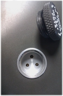
The mass positions are directly output by the instrument as analogue voltages in the range ±10 Volts. They are available at the bayonet connector where they can be monitored by a Güralp Systems digitiser (they appear as streams M8 (vertical), M9 (N/S) and MA (E/W) or by using the meter on the hand-held control unit. The offsets can be nulled using three potentiometers, located under a protective cover on the instrument's lid and adjustable using a trim-pot tool or a very small flat-bladed screwdriver.
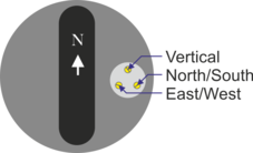
The cover can be removed without tools: three potentiometers are then exposed. The one nearest the “North” of the instrument controls the vertical mass offset and the other two, proceeding clockwise, control the North/South and East West offsets.
Select the component you want to centre using the CENTRING SELECT dial;
Switch the signal meter dial to one of the MASS POS settings;
Switch the rightmost switch to 1 SEC VEL to enable the centring lines;
Switch the RANGE selector to 10V (coarse adjustment);
Adjust the relevant potentiometer until the signal meter reads zero:
If the vertical mass position is too low, turn the adjuster anti-clockwise;
If the North/South mass position is too low, turn the adjuster anti-clockwise;
If the East/West mass position is too low, turn the adjuster clockwise.
The adjusters have a sensitivity of around 0.6 Volts per turn.
Switch the RANGE selector to 1V (fine adjustment);
Adjust the relevant potentiometer until the signal meter reads as close to zero as possible.
Change the rightmost switch back to the BB VEL position to re-enable broadband mode.
If there is a fault or if the instrument is too far from level, it may be impossible to null a mass position. In this case, the adjuster will continue to turn without making any further difference to the output. If you cannot resolve this by physically levelling the instrument, please contact GSL Support for advice.
3.4.1 Remote centring option (legacy)
Some instruments were fitted with a remote centring option. For these instruments, the mass position offsets were adjusted using a micro-controller and three digital potentiometers that replaced the standard electromechanical potentiometers.
On power-up, the micro-controller would automatically zero the mass positions of all three axes simultaneously. Zeroing could be further triggered via the “centre” control line on pin U. (Pin U is the 'Acc/Vel' line on instruments without the digital nulling option.)
Automatic zeroing took approximately forty-five seconds to complete, after which the sensor reverted to long period operation and the nulling module entered a low power “sleep” mode. During nulling, the sensor's outputs would fluctuate as the pots were adjusted in a binary search before settling with a mass position of ±0.5V. If the sensor was poorly levelled, the micro-controller would make three attempts to zero the mass before giving up and using the closest match.
A test mode was available to check the operation of the digital centring pots. This mode was entered by holding the centre line low during power up. The unit would then set the pots to maximum for thirty seconds; then minimum for thirty seconds; then to the centre position for six minutes. The centre line had to be held low continuously, otherwise the unit would abort the test mode and null the sensors as normal.
3.5 Test installation
This section gives an overview of how to set up a Güralp 6T and begin recording data. We recommend that you set up a test instrument in your office or laboratory as a “dry run” to gain a basic understanding of the system and to check that it is functioning as expected.
This test installation will use the instrument's default settings. Data will be digitised using a Güralp DM24 and received using Güralp Systems' Scream! software, available from our website
You will need access to a PC with a 9-pin RS232 port, and a 12 V power source.
Install Scream! on your PC and run it.
Connect the GNSS receiver to the DM24 using the brown cable supplied with the digitiser. Position the GNSS receiver so that it has a good view of the sky. If you do not have a view of the sky, you can operate the sensor without a GNSS receiver, but timing information may be inaccurate.
Connect the grey data cable between the 6T and the SENSOR A connector on the digitiser.
Using the blue/grey combined data/power cable that is included with the DM24, connect the digitiser to the PC's serial port and then to a 12V power supply.
The instrument is now fully operational, and will already be producing data.
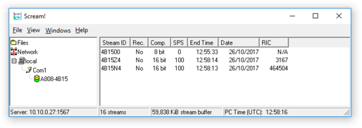
After a few seconds you should see the digitizer appear under Network – Local – Com1 in the left-hand panel of Scream!'s main window. (If your PC has multiple serial ports, it may appear under some other Com port name.) Soon after, data streams will begin appearing in the right-hand panel. Streams with higher sample rates will appear sooner than those with lower sample rates.
If this does not happen, check all connections, and ensure the power supply is providing the correct voltage and current.
Each data stream has a Stream ID, a six-character string unique to it. Stream IDs normally identify the instrument, component and sample rate of each stream. Thus the stream 1026Z2 refers to a Z-component stream from instrument 1026, at tap 2.
Data streams ending in 00 and 01 are status streams containing any extra information sent from the digitizer. Streams with IDs ending in IB are InfoBlocks and can be configured to contain calibration information for the attached sensor. Please see the relevant digitiser manual for more information.
To view data, select a stream and then double-click to open a Waveview window.
You can view several streams at once by holding down
 as you select, and then double-clicking the selection.
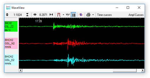
To start recording new data to a file, right-click on a stream or a selection of streams and choose Start recording from the pop-up menu. Recording settings, directories, etc., can be altered by selecting File → Setup... from the main menu and switching to the Recording tab.
3.6 Installation notes
For the best possible results, a seismometer should be installed on a seismic pier in a specially-built vault, where conditions are near perfect. Here, wave-trains arriving at the instrument reflect very well the internal motion of subsurface rock formations. However, this is not always feasible. For example,
instruments may need to be deployed rapidly, perhaps to monitor the activity of a volcano showing signs of rejuvenation, or to study the aftershocks of a major earthquake;
installations may be required in remote locations, or otherwise in circumstances where it is infeasible to build a vault.
In these situations, the seismometer and its emplacement need to be considered as a mechanical system, which will have its own vibrational modes and resonances. These frequencies should be raised as high as possible so that they do not interfere with true ground motion: ideally, beyond the range of the instrument. This is done by
standing the sensor on bedrock where possible, or at least deep in well-compacted subsoil;
clearing the floor of the hole of all loose material; and
using as little extra mass as possible in preparing the chamber.
In temporary installations, environmental factors are also important. The sensor needs to be well protected against
fluctuations in temperature,
turbulent air flow around walls or trees, or around sharp corners or edges in the immediate vicinity of the sensor;
vibration caused by heavy machinery (even at a distance), or by overhead power lines.
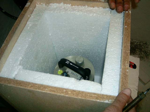
This can be done by selecting a suitable site, and placing the instrument in a protective enclosure. An open-sided box of 5 cm expanded polystyrene slabs, placed over the instrument and taped down to exclude draughts, makes an excellent thermal shield.
After installation, the instrument case and mounting surface will slowly return to the local temperature, and settle in their positions. This will take around four hours from the time installation is completed.
3.7 Installing in vaults
You can install a Güralp 6T in an existing seismic vault with the following procedure:
Unpack the sensor from its container, saving the shipping boxes for later transportation.
Prepare the mounting surface, which should be smooth and free of cracks. Remove any loose particles or dust, and any pieces of loose surfacing. This ensures good contact between the instrument's feet and the surface.
If it is not already present, inscribe an accurate North-South line on the mounting surface.
Place the sensor over the scribed line, so that the brass and steel pointers are aligned with the marked directions, with the brass pointer facing North. This can be done by rotating the base of the sensor whilst observing it from above. The brass pointer can be found next to one of the feet.
If you cannot easily see the pointers, you should align the sensor using the north arrow on the handle. However, the alignment of the handle with the sensors inside is less accurate than the metal pointers, so they should be used wherever possible.
The top panel of the Güralp 6T includes a spirit level.
Level the sensor using each of the adjustable feet of the instrument in turn, until the bubble in the spirit level lies entirely within the inner circle. (The instrument can operate with up to 2 ° of tilt, but with reduced performance.)
The feet are mounted on screw threads. To adjust the height of a foot, turn the brass locking nut anticlockwise to loosen it, and rotate the foot so that it screws either in or out. When you are happy with the height, tighten the brass locking nut clockwise to secure the foot.
When locked, the nut should be at the bottom of its travel for optimal noise performance.

Connect the grey sensor cable to the digitiser.
Connect a GNSS receiver, a PC and a 12 V fused power supply to the digitiser.
Run Scream! on the PC and check that data are being produced. Optionally, also check the mass position outputs (streams ending M8, M9 and MA.) These streams are digitized at a slower rate, and may take up to 15 minutes to appear.
Cover the instrument with thermal insulation, for example, a 5 cm expanded polystyrene box. This will shield it from thermal fluctuations and convection currents in the vault. It also helps to stratify the air in the seismometer package. Position the thermal insulation carefully so that it does not touch the sensor package.
Ensure that the sensor cable is loose and that it exits the seismometer enclosure at the base of the instrument. This will prevent vibrations from being inadvertently transmitted along the cable.
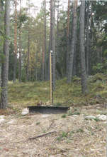
3.8 Installing in pits
For outdoor installations, high-quality results can be obtained by constructing a seismic pit.
Depending on the time and resources available, this type of installation can suit all kinds of deployment, from rapid temporary installations to medium-term telemetered stations.
Ideally, the sensor should rest directly on the bedrock for maximum coupling to surface movements. However, if bedrock cannot be reached, good results can be obtained by placing the sensor on a granite pier on a bed of dry sand.
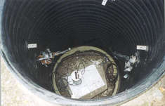
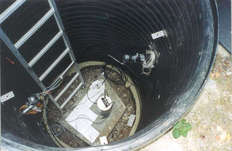
Prepare a hole of 60 – 90 cm depth to compacted subsoil, or down to the bedrock if possible.
On granite or other hard bedrock, use an angle grinder to plane off the bedrock at the pit bottom so that it is flat and level. Stand the instrument directly on the bedrock, and go to step 7.
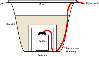
On soft bedrock or subsoil, you should install a pier as depicted below.
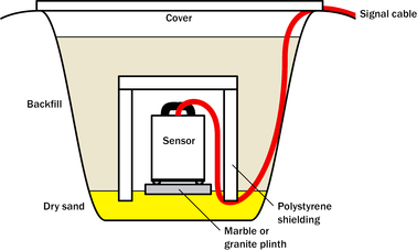
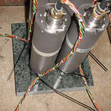
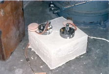
Pour a layer of loose, fine sand into the pit to cover the base. The type of sand used for children's sand-pits is ideal, since the grains are clean, dry and within a small size range. On top of the sand, place a smooth, flat granite plinth around 20 cm across, and shift it to compact the sand and provide a near-level surface.
Placing a granite plinth on a sand layer increases the contact between the ground and the plinth, and improves the performance of the instrument. There is also no need to mix concrete or to wait for it to set.
Alternatively, if time allows and granite is not available, prepare a concrete mix with sand and fine grit, and pour it into the hole. Agitate (“puddle”) it whilst still liquid, to allow it to flow out and form a level surface, then leave to set. Follow on from step 7.
Puddled concrete produces a fine-textured, level floor for situating the seismometer. However, once set hard, the concrete does not have the best possible coupling to the subsoil or bedrock, which has some leeway to shift or settle beneath it.
Alternatively, for the most rapid installation, place loose soil over the bottom of the pit, and compact it with a flat stone. Place the seismometer on top of this stone. This method emulates that in step 3, but can be performed on-site with no additional equipment.
Set up the instrument as described in Section 3.7, page 14 (steps 4 to 9).
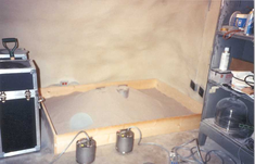
The instrument must now be shielded from air currents and temperature fluctuations. This is best done by covering it with a thermal shield.
An open-sided box of 5 cm expanded polystyrene slabs is recommended. If using a seismic plinth on sand (from steps 3–4 or 5), ensure that the box is firmly placed in the sand, without touching the plinth at any point. In other installations, tape the box down to the surface to exclude draughts.
Alternatively, if a box is not available, cover the instrument with fine sand up to the top.
The sand insulates the instrument and protects it from thermal fluctuations, as well as minimizing unwanted vibration.
Ensure that the sensor cable is loose and that it exits the seismometer enclosure at the base of the instrument. This will prevent vibrations from being inadvertently transmitted along the cable.
Cover the pit with a wooden lid, and back-fill with fresh turf.
3.9 Other installation methods
The recommended installation methods have been extensively tested in a wide range of situations. However, past practice in seismometer installation has varied widely.
Some installations introduce a layer of ceramic tiles between a rock or concrete plinth and the seismometer (left):
However, noise tests show that this method of installation is significantly inferior to the same concrete plinth with the tiles removed (right). Horizontal sensors show shifting due to moisture trapped between the concrete and tiling, whilst the vertical sensors show “pings” as the tile settles.
Other installations have been attempted with the instrument encased in plaster of Paris, or some other hard-setting compound (left):
 Again, this method produces inferior bonding to the instrument, and moisture becomes trapped between the hard surfaces. We recommend the use of fine dry sand (right) contained in a box if necessary, which can also insulate the instrument against convection currents and temperature changes. Sand has the further advantage of being very easy to install, requiring no preparation.
Finally, many pit installations have a large space around the seismometer, covered with a wooden roof. Large air-filled cavities are susceptible to currents which produce lower-frequency vibrations, and sharp edges and corners can give rise to turbulence. We recommend that a wooden box is placed around the sensor to protect it from these currents. Once in the box, the emplacement may be backfilled with fresh turf to insulate it from vibrations at the surface, or simply roofed as before.