Chapter 3. Procedure
3.1 Equipment required
The following equipment is required:
2 mm hexagonal wrench (Allen key).
2.5 mm flat-bladed screwdriver.
Anti-static wristband.
12 volt regulated DC power supply.
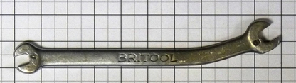
Modified spanner (see section 4):
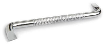
Offset screwdriver:
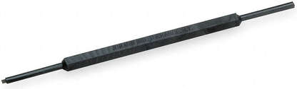
Trim-pot adjusting tool:
For 6Ts: a sensor cable and hand-held controller (HCU). For 6TDs: a test cable, as discussed in the previous section, and either an HCU or a voltmeter.
3.2 Disassembly
Make alignment marks on the base, casing and lid so that they can be re-assembled in the correct orientation.
Mark the position of the instrument's feet on the workbench so that it can be returned to the same position after manipulation.
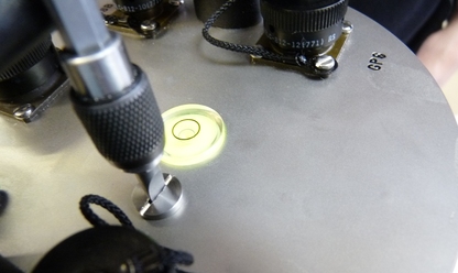
Level the instrument using the adjustable feet until the bubble on the lid is within the engraved ring on the indicator. Check with an external spirit level laid across the instrument's lid. If the built-in bubble level is inaccurate, remove and replace it.
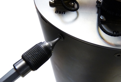
Using the flat-bladed screwdriver, remove the pressure relief screw from the top of the lid as shown below.
Warning: GSL instruments are assembled at sea level. When servicing the instrument at altitude, there may be a considerable pressure differential between the air inside the casing and the external atmosphere. This could cause the screw to fly off with considerable force when initially released. Take care that this does not cause injury.
Using a 2mm hexagonal wrench, remove the screws attaching the lid to the casing as shown below:
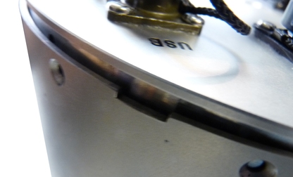
Lever off the lid by placing a flat headed screwdriver in the notches provided and twisting.
Caution: The force required will drop significantly when the O-ring seals become clear of the the top of the cylinder. Take particular care that the lid does not “fly off” when this happens.
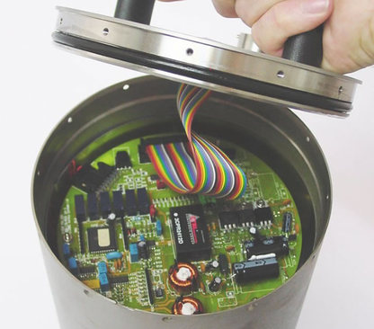
Lift the lid away from the casing.
Whilst wearing an anti-static wrist-band, disconnect (at either end) the ribbon cable between the lid and the lower electronics.
Using a 2mm hexagonal wrench, remove the screws attaching the the casing to the instrument base plate.
Carefully lever off the casing from the baseplate using a flat headed screwdriver.
Lift off the casing slowly and vertically taking care not to knock or jar the mechanical components inside.
3.3 Centring the sensors
Using an analogue lid supported next to the instrument or an analogue test cable, connect the instrument to a Güralp HCU and apply power. If recentring a 6TD, connect the analogue test cable between the uppermost circuit board in the instrument and the HCU.
Set the HCU to 10V and 1sec.
Rotate the dial to the sensor under test (V, N/S or E/W).
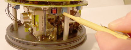
Adjust the centring potentiometer on the PCB and note the deflection limit in either direction on the display.
If the readings are equal in both directions the sensor is correctly centred. Go to step 12.
If the readings are not equal in both directions, add the readings together and divide by 2.
Adjust the potentiometer to the largest deflection limit.
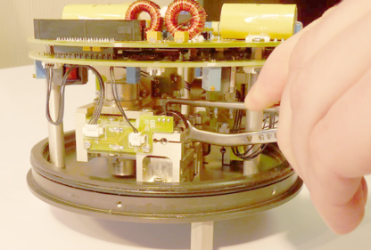
Slightly loosen the locking screw on the hexagonal centring spindle so that it remain stiff to move but can be adjusted with the modified spanner. On sensors where the locking screws are mounted vertically use an offset screwdriver to loosen the screw.
Adjust the position of the hexagonal centring bar so that the needle moves to the figure calculated at step 6.
For example: If the deflections in either direction are 5 and 1 the sum will be 6. Divided by two gives a result of 3. Adjust the potentiometer to give deflection of 5. Adjust the hexagonal centring spindle until the meter reads 3.
Tighten the screw to lock the position of the hexagonal centring spindle.
Go to step 4.
Repeat centring procedure for each sensor in the instrument.
Turn off the power supply.
Disconnect the HCU, analogue lid and/or analogue test cable, as appropriate.
3.4 Re-assembly
Check that the lower 'O'-ring seal is clean. Re-grease if necessary.
Lower the casing over the internal sensor components.
Align the casing with the marks made during disassembly.
Loosely install all the case securing screws then tighten.
Caution: Tighten only enough to secure the screws and do not over-tighten. If you distort the cylinder, you will compromise the seal.
Whilst wearing an anti-static wrist-band, re-connect the ribbon cable between the lid and the lower electronics.
Check that the upper 'O'-ring seal is free from contamination and re-grease if necessary.
Install the instrument lid, aligning the marks made during disassembly. If the marks have rubbed off or are not clear, align the north end of the handle with the pointer on the base of the instrument.
Loosely install all the lid-securing screws then tighten.
Caution: Tighten only enough to secure the screws and do not over-tighten. If you distort the cylinder, you will compromise the seal.