Chapter 4. Appendices
4.1 6TD analogue test cable for use with break-out box
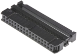
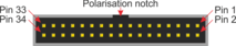
This is a standard 34-way IDC connector with 2.54 mm (0.1 inch) pitch. It is available from many manufacturers. An example is Amphenol part number T812134A101CEU. |
| |
| Pin numbering for the IDC connector, as seen when looking into the circuit-board-mounted connector. Pin 1 is usually indicated by a 'V' marked on the body of the connector. | |
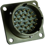
This is a standard 26-pin military specification bayonet plug, conforming to MIL-DTL-26482 (formerly MIL-C-26482). A typical part-number is 02E-16-26P although the initial “02E” varies with manufacturer. |
| |
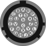
| Wiring details for the bayonet plug, as seen from the cable end (i.e. when assembling). | |
Note: Only the connections shown with a tick (✔) in the Req column below are required in this application. Adding the other connections (those marked ✘) will also allow the analogue part of a 6TD instrument to be tested independently from the digitiser.
26-pin bayonet | Function | Req | 34-way IDC |
A | Z velocity output + (non-inverting) | ✘ | 22 |
B | Z velocity output - (inverting) | ✘ | 18 |
C | N/S velocity output + (non-inverting) | ✘ | 22 |
D | N/S velocity output - (inverting) | ✘ | 21 |
E | N/S velocity output + (non-inverting) | ✘ | 25 |
F | N/S velocity output - (inverting) | ✘ | 24 |
G | Z mass position output | ✔ | 20 |
J | N/S mass position output | ✔ | 23 |
L | E/W mass position output | ✔ | 26 |
N | Signal ground | ✔ | 29 |
P | Calibration signal | ✘ | 27 |
R | Calibration enable | ✘ | 28 |
U | One-second mode | ✔ | 16 |
b | Power supply ground | ✔ | 3, 5, 7 |
c | Power supply +V | ✔ | 1, 2, 4 |
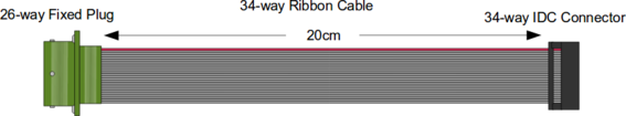
4.2 6TD analogue test cable for use with voltmeter
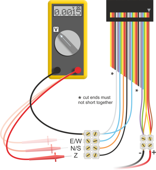
This cable is most easily constructed by modifying an existing 34-way ribbon cable with IDC headers. If a "rainbow" cable is used, selecting the required cores is significantly easier.
This is a standard 34-way IDC connector with 2.54 mm (0.1 inch) pitch. It is available from many manufacturers. An example is Amphenol part number T812134A101CEU. |
| |
| Pin numbering for the IDC connector, as seen when looking into the circuit-board-mounted connector. Pin 1 is usually indicated by a 'V' marked on the body of the connector. | |
Function | Colour | Core number |
Z mass position output | Black | 20 |
N/S mass position output | Orange | 23 |
E/W mass position output | Blue | 26 |
Signal ground | White | 29 |
One-second mode | Blue | 16 |
Power supply ground | Orange, Green, Violet | 3, 5, 7 |
Power supply +V | Brown, Red, Yellow | 1, 2, 4 |
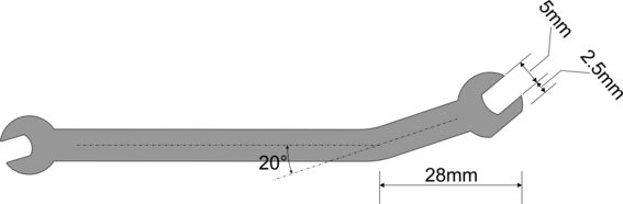
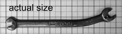
4.3 Modified spanner details
The modified spanner can be constructed from a standard 5 mm open-ended spanner by hot bending and grinding it as shown.