Chapter 2. Introduction
2.1 Important notice
The information in this document is believe to be correct at the time of writing. The information in our possession, however, is currently changing daily. Please look on our web-site to ensure that you have the latest version of this document before commencing any work. The latest version will be posted at:
https://www.guralp.com/documents/PRC-GPS-0001.pdf
2.2 Overview
Güralp GPS receivers have historically used a number of different chip-sets from different manufacturers. The original design of the US' Navstar GPS system had a fundamental flaw known as the Week-Number Roll-Over problem or WRNO (see section 4.1) which means that some of these chip-sets will cease to function properly after certain dates.
In particular, we have been informed that two chip-sets will fail in the near future:
the Trimble Lassen SQ®, used between 2003 and 2010, will cease to operate correctly on the 28th of July, 2019; and
the Trimble Lassed iQ®, used between 2010 and February 2015, will cease to operate correctly on the 29th of May, 2021.
GPS receivers supplied since February 2015, identifiable by a serial number beginning G3…, use chip-sets manufactured by u-blox® and will not be affected by the WNRO.
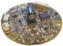
This document explains how to replace a PCB assembly within the GPS receiver in order to convert Trimble-based units to use the u-blox chip-set.
Caution: The digitiser with which the upgraded receiver is being used must be upgraded to run the latest firmware if it is not already running it. Please refer to our web page at www.guralp.com/support/firmware for the latest information.
2.3 Scope
These instructions apply only to GPS receivers containing Trimble Lassen SQ®, or Trimble Lassen iQ®, chip-sets. These can be identified either by visual inspection or by analysis of their NMEA output. For information about identification techniques, please see section 4.2.
2.4 Prerequisites
2.4.1 Tools and facilities
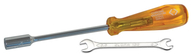
The following tools and facilities are required:
anti-static workstation and wrist-band
 ;
;small strap-wrench
 ;
;selection of common screw-drivers and hex wrenches
 ; and
; andM3 nut-driver or 5 mm spanner
 .
.
2.4.2 Materials
The following materials are required:
Replacement PCB assembly
 ; and
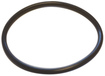
; andReplacement pre-greased O-ring seal
 .
.
Caution - ESD : The replacement PCB assembly includes components which can be damaged by electrostatic discharge. Always work on a properly grounded dissipative surface and wear a suitable grounded wristband. Ground yourself by touching an earthed conductor before handling the assembly.