Chapter 3. The procedure
Proceed according to the directions below. If you encounter problems, please do not proceed: stop and contact Güralp support (via an email to support@guralp.com). It will normally be very helpful if you can include photographs illustrating the problem you have experienced.
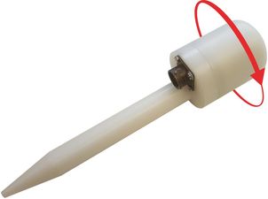
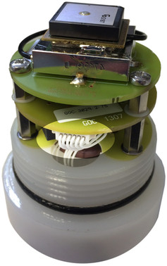
Remove the cap of the GPS assembly by unscrewing it:
If the cap is difficult to remove, try bracing the spike and connector against the edge of the bench:
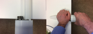
Rubber gloves may be helpful to give you a better grip.
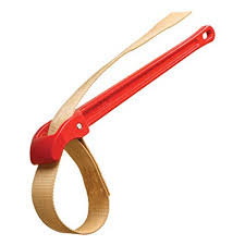
In extreme cases, use a strap-wrench:
Check that the PCB assembly contains either a Trimble Lassen SQ®, or Trimble Lassen iQ® by comparing it with the images below:
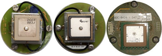
The three receivers shown contain, from left to right,
Trimble Lassen SQ® (cream/ceramic-coloured module with silver top)
Trimble Lassen iQ® (black module with silver top)
u-blox PAM 7Q (brown module with silver top)
Note: Only proceed if you have one of the two Trimble Lassen®-based PCBs. If you have a receiver based on the u-blox chip-set, as shown on the right above, you will not be affected by the WRNO and you do not need to replace the PCB assembly.
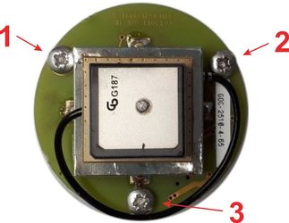
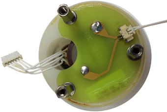
Identify the 6 way connector on the middle circuit board:
Disconnect it by grasping the connector on each side and pulling:
Using an appropriate tool, remove the three screws and washers holding the top circuit board in place. Retain these components for re-fitting.
Note: The actual fasteners used may be different from those shown. You may encounter PZ2 cross-head screws, 5 mm flat-head screws, M3 hex-socket screws or another fastener. This makes no difference to the operation of the unit.
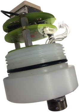
Remove the top circuit board assembly by lifting it upwards and to one side:
Using a 5 mm nut-spinner or spanner, unscrew and remove the three short stand-off pillars and set them aside.
Remove the middle circuit board assembly by lifting it upwards. Set it aside.
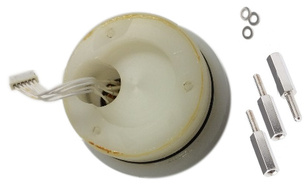
Using a 5 mm nut-spinner or spanner, unscrew and remove the three long stand-off pillars. Retain these components for re-fitting.
Remove the bottom circuit board assembly by lifting it upwards. Set it aside.
Using a 5 mm nut-spinner or spanner, re-fit the long stand-off pillars to the receiver body, placing a metal washer between the bottom of each stand-off pillar and the body.
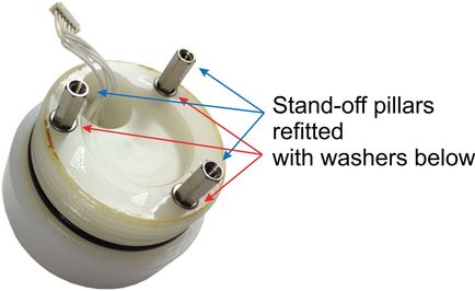
Caution: Tighten the stand-off pillars only until they are secure. Over-tightening may result in the threads being stripped. If this happens, you can use a little super glue or a little epoxy resin to repair the thread and hold the stand-off in place.
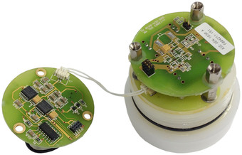
Using an anti-static wrist band and an appropriate screw-driver, fit the new U-blox PAM-7 circuit board assembly onto the stand-off pillars using the three screws removed previously. Do not over-tighten. Take care to orientate the board relative to the base as shown in the photograph below.
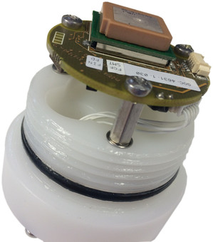
Connect the 6 way connector to the PAM-7 circuit board.
Remove the old O-ring from the receiver body and discard it. Check the groove where it lay for any grit, dust or contamination and clean if necessary.
Check the new O-ring seal for any grit, ensure that the grease is evenly distributed and then fit the new O-ring to the receiver body
Finally, re-fit the top cover to the receiver body, taking care not to cross the threads.
Caution: Do not use tools. Hand tighten only.
The GPS/GNSS receiver is now ready to be tested.
Caution: The digitiser with which the upgraded receiver is being used must be upgraded to run the latest firmware if it is not already running it. Please refer to our web page at www.guralp.com/support/firmware for the latest information.