Trouble-shooting GNSS/GPS problems
Overview
Güralp digitisers use Global Navigation Satellite Systems (GNSS) to synchronise their sample clocks. This is the most accurate time-source available other than atomic clocks which are expensive and impractical in most circumstances. Güralp GNSS receivers are available for use with the US GPS (formerly Navstar) constellation, the Russian GLONASS constellation, the Chinese BeiDou constellation and, when it becomes available in 2020, the European Galileo constellation.
For best results, Güralp GNSS receivers need to have a clear view of the sky, unobstructed by buildings and foliage. Because they are fully exposed to the elements, the receiver and associated cable are, potentially, the most vulnerable part of an installation. Damage due to animals, vandalism and electric storms have all been reported. If you have problems with GNSS synchronisation, this guide is intended to help you trouble-shoot.
The guide has been split into several pages to cover different combinations of equipment. This page covers white receivers with 6-pin connectors used with CD24 digitisers, 6TD instruments and 3ESPCD instruments with 6-pin GPS connectors. Other pages are available for other combinations of equipment, as detailed in the following list:
Terminology
The following terms are used throughout this document:
- SoH - State of Health. This term is used to refer to information about the status of an instrument, such as its mass positions, and information about the status of a digitiser, such as whether its sample clock is locked or not.
- GNSS - Global Navigation Satellite System. This is a generic term for any of a number of systems which use constellations of satellites, each fitted with an extremely accurate atomic clock, to provide signals to earth-based receivers. This allows the receivers to use the signal propogation delays to compute position to an accuracy of a few metres and time to an accuracy of a few microseconds.
- GPS - Global Positioning System. Although this term properly refers only to the US-operatated GNSS (formerly called "NavStar"), it is often used as a synonym for GNSS. Timing systems for Güralp digitisers were initially developed for use only with the GPS system and many of the commands and messages reflect this fact. The connectors are labelled GPS even on equipment which supports multiple GNSS constellations. Within this document, if there is any doubt, the context should make it clear to which system we refer.
- Constellation - This is the formal term for the collection of active satellites that form the space-based sector of a GNSS.
- SV - This is an abbreviation for Space Vehicle, the
formal term for a satellite in a GNSS constellation. Each
satellite in a constellation has a unique identification number,
referred to as its "SV#". These are allocated
in ranges as follows:
1 — 32 Navstar/GPS 65 — 88 GLONASS 89 — 96 GLONASS
(future extensions)301 — 336 Galileo 401 — 437 BeiDou - NMEA - This initialism for the National Marine Electronics Association is used (in this context) as an abbreviation for the NMEA 0183 standard for marine communications. It is the most common standard used for transmitting time, position and other information from GNSS receivers. It consists of a series of formatted text messages called "sentences" which provide operational and status information. The NMEA from a GNSS receiver contains information such as the time, date, location, fix status (see below), number of satellites visible and accuracy of calculations.
- PPS - An abbreviation for one-Pulse-Per-Second, this term describes a pulse train sent by the GNSS receiver to the digitiser. The leading edge of each pulse accurately identifies the start of each second. Subsequent NMEA sentences make explicit the time and date of the second thus indicated.
- FIX - When a GNSS receiver has computed a position, it is described as having obtained a "fix". When satellite visibility is limited, a first approximation can be made by assuming that the receiver is near sea-level (actually: on the surface of the WGS84 reference elipsoid). This is referred to as a two-dimensional or "2D" fix. When signals from a sufficient number of satellites are being received, a full three-dimensional fix, which includes elevation is achieved. This is known as a "3D" fix.
- GNSS power-cycling - This is a Güralp-specific firmware feature intended to reduce power consumption in power-critical applications. The user can specify a time period, n of between one and twenty-four hours. The GNSS receiver is powered up at boot and every n hours thereafter. Each time it is powered up, the system resynchronises, if necessary, and then waits until the offset and drift have fallen to acceptable levels. It then powers the receiver down again before repeating the cycle.
- Status stream - For CD24 and DM24 digitisers, along with all equipment containing them, this is a textual stream which contains state-of-health information about the digitiser, including the GNSS and sample-clock. The term is also used loosely to refer to status information available from the console of the Minimus and Fortis.
Contents
Table
of
Contents
- Overview
- Contents
- Accessing the status stream
- Interpreting the status stream
- Monitoring NMEA contents
- Configuration problems
- Diagnosis by replacement
- Diagnosis by test
- Testing the Break-out Box
- Further reading
Accessing the status stream
The status stream from a CD24 digitiser can be inspected using Scream. If it is connected via an EAM, you can also access the status stream using the EAM's web interface or command-line.
Using Scream
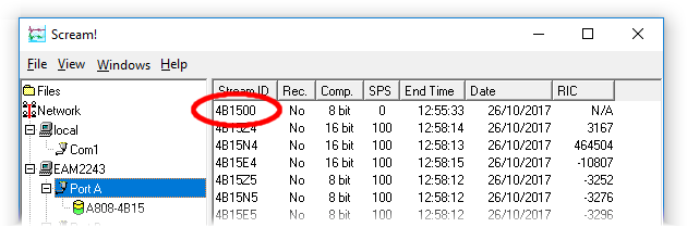
Scream displays all streams in the right-hand pane of its main window. If you select a digitiser from the list in the left hand pane - the source tree - the right-hand side of the display will show only streams from the selected digitiser. Once you have selected the digitiser of interest, the status stream can be identified by its name, which will end with two zeros: 00. Note also that the sample rate will be shown as zero (because this is a textual stream) and the RIC will be shown as N/A for the same reason.
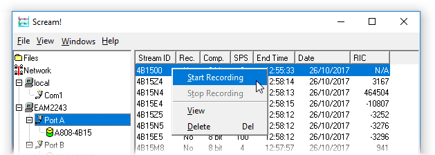
If there is a yes in the column headed Rec., the status stream is being recorded by Scream (typically to the local PC, although this is configurable) and you can view previous entries from the configured recording destination: please see the Scream manual for more information. To enable recording, right-click on the stream name and select Start Recording from the context menu.
To view live status stream entries, double-click on the stream name in Scream's main window or select View from the context menu. A new window will open showing the most recent entries:
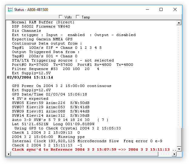
The screen will be updated in real time: as packets arrive via the status stream, they will be displayed in this window. Note that, although some significant events will trigger the immediate output of a status packet, individual messages in the status stream are normally collected in the digitiser until 1 kB are available before they are packed and transmitted so, depending on how busy or otherwise the traffic on the stream is, it may take several minutes to receive an update.
To avoid this delay when diagnosing problems, open a terminal window
by right-clicking on the digitiser's icon
(![]() )
in the source tree and selecting Terminal...
from the context menu:
)
in the source tree and selecting Terminal...
from the context menu:

When the terminal window opens, enter the commands OK-1 and flush-status:
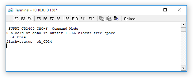
Then enter the command go to close the terminal window. Any outstanding status messages will be sent within a second or two and they will appear in the status stream window, if it is still open.
Using an EAM's web interface
If the output of your digitiser is routed through an EAM or if you are using a digitiser or instrument with an integrated EAM, the status stream from the digitiser is recorded by the EAM and included in its own status-recording mechanisms.
You can view the status stream from a connected digitiser using the "System status" screen of the web interface. Start by ticking the "Show hidden values" check-box at the bottom of the screen. Once the display has refreshed, click the tab for the digitiser in question: this will be labelled with the System ID and Serial number of the digitiser.
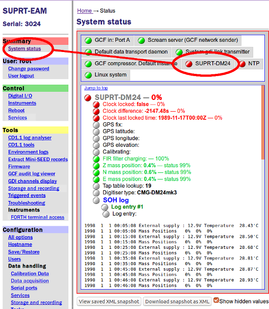
The status stream is recorded in the "Log entry" sections labelled SOH log where "SOH" stands for "State Of Health", the traditional name for status information.
Using an EAM's command line
If the output of your digitiser is routed through an EAM or if you are using a digitiser or instrument with an integrated EAM, the status stream from the digitiser is recorded by the EAM and included in its own status-recording mechanisms.
The most recent status information from both EAM and digitiser is stored in the file /var/log/messages. When this file is full, it is renamed /var/log/messages.0 and a new /var/log/messages is started. In a similar fashion, any existing /var/log/messages.0 is renamed /var/log/messages.1 and so on until there are twenty files, numbered zero to nineteen, in addition to the current, live messages file.
Regardless of the actual type of digitiser used, the digitiser status stream entries in the messages file are prefixed with the EAM's time and date and the word DM24 followed by a colon (':). This allows the use of the grep command to extract just the digitiser status from the messages files. For example, the command
grep DM24: /var/log/messages
will extract the digitiser status entries from the latest messages file.
If you want the status entries from all messages files, the following command ensures that they appear in the correct order (oldest first):
grep DM24: `ls -rv /var/log/messages*`
Because this produces a lot of output, it is wise to pipe the output through a pagination program such as less. For example:
grep DM24: `ls -rv /var/log/messages*` | less
You can now view the output a page at a time by keying the spacebar. It is also possible to move backwards through the entries or to search for specific text: see the less manual page for more information.
Interpreting the status stream
The GNSS-related messages from these systems include:
- GPS Power On continuous This indicates that the digitiser is providing power to the GNSS receiver.
- GPS This indicates that NMEA and PPS are being received, which is the normal operational state. It appears at boot-up and whenever the power is restored during GNSS power-cycling.
- NO GPS This indicates that no PPS signal is being received. The receiver, cable and digitiser should be tested as described below.
- NO GPS MESSAGE This indicates that no NMEA sentences are being received. The receiver, cable and digitiser should be tested as described below.
- $PGSBB,Guralp Systems Ltd - UbloxGPS v1.0 mgs 08/09/15 (Build 1.08)*1F This is a Güralp manufacturer-specific sentence emitted by our latest generation of GNSS receivers.
- No FIX SV#'s none This message indicates that the GNSS receiver is not receiving satellite signals. Check the location and orientation of the receiver and ensure that it is not obscured by buildings or overgrowth.
- Auto 2-D SV#'s 3 6 20 ( 3 ) This message indicates that the GNSS receiver has received signals from three satellites: numbers 3, 6 and 20. The receiver has not, however, been able to compute a three-dimensional "fix" (hence 2D) so its calculated time is not yet sufficiently accurate to be used for synchronisation. If this situation persists, check the location and orientation of the receiver and ensure that it is not obscured by buildings or overgrowth. If it has a good view of the sky, the receiver may be faulty and should be replaced in order to verify the fault.
- Auto 3-D SV#'s 18 10 16 8 27 21 ( 6 ) - this indicates that the receiver has heard from six satellites and has computed a three-dimensional fix (latitude, longitude and height) which means that the receiver can now be used for synchronisation of the sample clock.
- Lat 19'54.0759N Long 019'21.1105E Height 00055M This message is normal and healthy. It displays the location (latitude, longitude in degrees, minutes and decimal fractions of minutes and height above the WGS84 reference ellipsoid in metres) as calculated by the GNSS receiver.
- 2018 1 11 10:20:38 Clock sync'd to GPS =>> 2018 1 11 10:20:39 - this indicates that the timing subsystem in the digitiser has successfully synchronised itself to the incoming data from the GNSS receiver. The "previous" time is shown at the beginning of the message and the receiver's time - the "new" and correct time - is shown at the end.
- o/s= 254 drift= -15 pwm= 11731
- Messages like this are printed to the status stream every minute
while the clock is synchronised and the timing subsystem is
working correctly. The values printed are:
- o/s - the offset between the sample clock and GNSS time, measured in units of 1/120 of a microsecond (8.33… ns). A feedback system monitors this number and adjusts the frequency of the crystal controlling the sample clock in order to minimise the offset.
- drift - the first derivative of the offset, which is also used as an input to the feedback system. It is the sum of the offsets over the preceding minute so it is expressed in units of (1/120)÷60 µs/s ≈ 1.79 ns/s.
- pwm - the output of the feedback system. This number is fed into a digital-to-analogue converter which generates a voltage which affects the oscillatory frequency of the crystal that controls the sample clock. This number is not usually of interest but, if the offset is growing steadily in magnitude and the pwm is not changing, this indicates that the crystal is out of specification and needs to be replaced. Contact for advice.
Monitoring NMEA contents
If there is doubt about the actual contents of the NMEA data stream, it is possible to inject the raw NMEA into the status stream so that it can be inspected. This feature is normally enabled for a few tens of seconds at most: the injection is then disabled and the status stream retrieved and inspected as outlined previously.
When connected directly (not via an EAM)
To enable injection of the raw NMEA into the status stream of a CD24 digitiser, issue the following commands:
2 MON !
GO
To disable injection, issue the commands:
1 MON !
GO
(Issuing
0 MON !
GO
will disable all NMEA reporting. The setting of 1 enables error notifications only.)
When connected via an EAM
In these systems, the NMEA signal from the GNSS receiver is routed through the EAM's Port C before processing by the digitiser. The stream can be viewed as a real-time data-stream from the command-line of the EAM. To do this, issue the command:
minicom PortC
An emulator window will open showing the live NMEA sentences scrolling in real-time. To exit the display, key Ctrl + A then Q.
For more information, please see the minicom manual page.
Configuration problems
It is possible to disable synchronisation by changing configuration settings. If you suspect that this might have happened, please check the following. There are three configuration options which affect the timing subsystem:
GPS-TYPE
Syntax: type GPS-TYPE
The value of type should be 2 for correct operation. A value of 0 means that GNSS signals will be ignored. If in doubt, enter 2 GPS-TYPE at the command line of the digitiser to ensure that the setting is correct.HR-CYCLE
Syntax: interval HR-CYCLE
This setting controls whether the GNSS receiver is powered on continually or whether the power is turned off once synchronisation is achieved, in order to save power. If there is doubt about the correct operation of the GNSS receiver, disable GNSS power-cycling by entering the command 0 HR-CYCLE. The value of 0 selects continuous power to the receiver.XGPS
Syntax: 0 | 1 XGPS
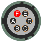
This setting manually switches on and off the GNSS subsystem, over-riding any HR-CYCLE setting. Issuing the command 0 XGPS turns the receiver off (and you should hear the associated relay inside the digitiser click as it is operated) and issuing the command XGPS turns it on again.By using this command to disable and re-enable the GNSS power while measuring the voltage between pins A and F of the receiver connector on the break-out box, it is possible to verify operation of the relay and the provision of power to the receiver. If you cannot confirm a 5 volt DC positive output on pin A, relative to pin F, proceed to check the break-out box. If the break-out box functions correctly , the digitiser or instrument is faulty: contact for advice.
Diagnosis by replacement
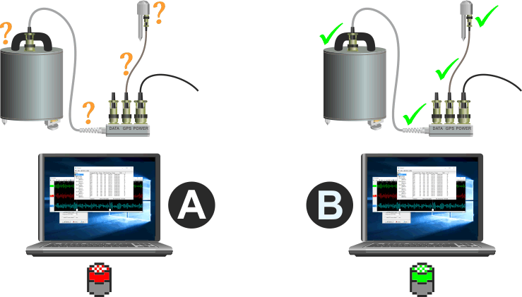
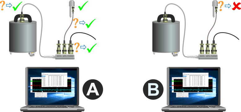
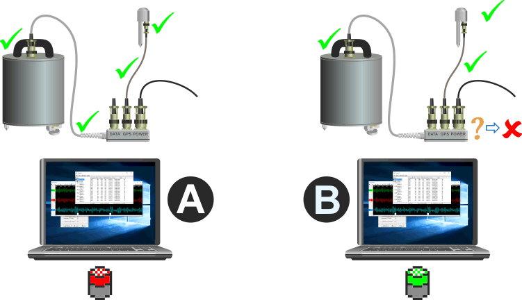
This technique is suitable if you have no test equipment but you do have either (a) another installation nearby which is working correctly or (b) equivalent equipment which you know works correctly. In the discussion below, we shall call the installation under test A and the working system B.
Note that, because the problem could be in either the receiver, the receiver cable, the break-out box or the instrument itself, we have to consider the status of all four of these components to be unknown, as indicated by the amber question-marks (?) in the diagrams below. The components of the working system, however, are all known to be good, as indicated by the green ticks (✔) in the diagrams.
The status of the complete system are, in each case, indicated by the Scream
digitiser icons, where the colour of the top half of the icon indicates the
synchronisation status: green
(![]() )
for synchronised and red
(
)
for synchronised and red
(![]() )
for unsynchronised. These icons are used to indicate test results in the diagrams
below.
)
for unsynchronised. These icons are used to indicate test results in the diagrams
below.
Checking the receiver
The first step is to interchange the GNSS receivers:
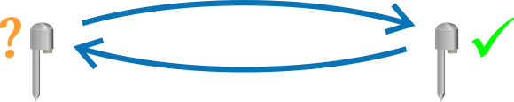
There are two possible outcomes: system A will start working and system B will stop working or there will be no change in symptoms.
If system A starts working
Because the only change we have made to system A is to add the known-good receiver from system B, it is clear that the receiver originally attached to system A must be faulty. We have also verified that system A's cable, break-out box and instrument work correctly, so the status of all components is now known:
The faulty GNSS receiver (now attached to system B) should be replaced.
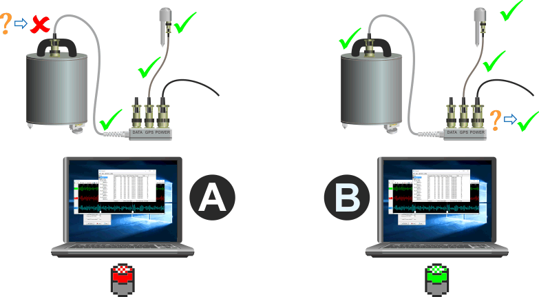
If there is no change
Because system B is still working, we now know that the receiver originally attached to A was not the cause of the problem. We can mark both receivers as good and restrict our investigation to system A's cable, break-out box and instrument, the statii of which are still unknown:
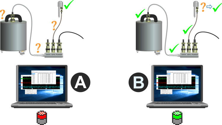
Continue by checking the cables, as described in the next section.
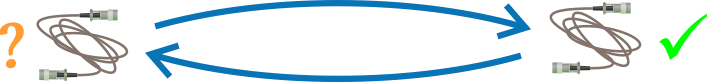
Checking the cable
The next step is to interchange the cables:
Again, there are two possible outcomes: system A will start working and system B will stop working or there will be no change in symptoms.
If system A starts working
Because the only change we have made to system A is to add the known-good cable from system B, we can see that the cable originally attached to system A must be faulty. We have also verified that system A's break-out box and instrument work correctly, so the status of all components is now known:
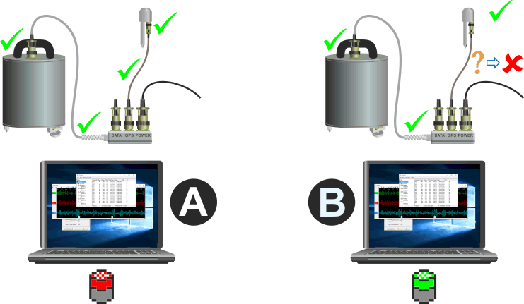
If there is no change
Because system B is still working, we now know that the cable originally attached to A was not the cause of the problem. We can mark both cables as good and restrict our investigation to system A's break-out box and the instrument itself, the statii of which are still unknown:
Continue by checking the break-out box, as described in the next section.
Checking the break-out box
The next step is to interchange the break-out boxes:

Again, there are two possible outcomes: system A will start working and system B will stop working or there will be no change in symptoms.
If system A starts working
Because the only change we have made to system A is to add the known-good break-out box from system B, we can see that the break-out box originally attached to system A must be faulty. We have also verified that system A's digitiser and break-out box work correctly, so the status of all components is now known:
If there is no change
Because B is still working, we know that the break-out box originally attached to A was not the cause of the problem. We can mark both break-out boxes as good so the only remaining possibility is that the instrument in system A is the cause of the problem:
Diagnosis by test
If you have a large fleet of installations, it may be worth a small investment in test equipment. An adaptor cable can provide power to the GNSS receiver while routing the NMEA to a PC for display and simultaneously indicating the PPS using an LED. This allows a receiver to be tested without the use of a digitiser.
The cables shown below use socket(s) to connect to the receiver(s) via the existing receiver cables. It is just as easy to use plugs, so that they can be connected directly to the receiver or, if you wish, both plugs and sockets wired in parallel so that receivers can be tested either with or without their associated cables.
All bayonet connectors are compatible with MIL-DTL-26482. Suitable connectors include the ITT/Cannon KPT series, the Amphenol PT series and the Souriau UTS series.
All of the cables use FTDI serial⬄RS232 conversion cables in order to allow direct connection to the USB port of a PC or laptop. Both of the types mentioned below are described in the FTDI USB to RS232 Serial Converter Range data-sheet.
Test cables
Special test cable for six-pin receivers

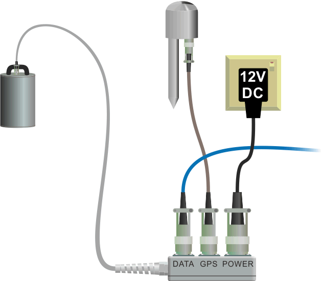
The cable illustrated below can be used with white, six-pin receivers. Because these receivers require a 5 volt DC power-supply, USB power can be used directly and there is no need for an independent power supply. The FTDI cable shown exposes a 5 volt output on the red wire.
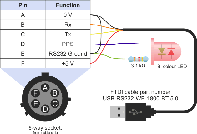
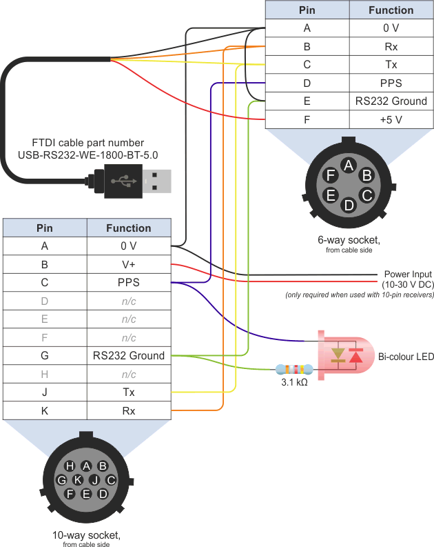
Universal test cable

If you have a mixture of six-pin and ten-pin receiver types, the following cable can be used to test them all. It incorporates the same FTDI cable as used in the 6-pin version to provide the required 5 volt DC supply.
Using a test cable
Connect the GPS receiver to the test cable and plug the USB connector into your PC or laptop.
On the PC or laptop, open a terminal emulator. Minicom is recommended for Linux PCs and PuTTY is recommended for Windows PCs but most emulators will work satisfactorily.
Configure the emulator for:
- 4800 Baud (but see note below)
- 8 data bits
- no parity
- 1 stop bit
- no hardware flow control (i.e. no RTS/CTS or DTR/DTS)
- no software flow control (i.e. no XON/XOFF)
The test configuration should look like this:
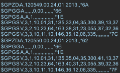
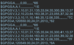
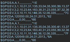
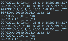
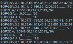
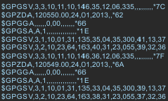


You should see NMEA data on screen. NMEA is an ASCII format so all characters should be legible and form one-line "sentences", each beginning with a dollar sign ($) followed by two further characters and ending with an asterisk (*) followed by two further characters.
The two characters following the initial $ are the "talker ID". This will be GP for GPS/NAVSTAR messages, BD for BeiDou messages, GP for GLONASS messages, GN for mixed GPS/NAVSTAR and GLONASS messages and, once it becomes available, GA for Galileo messages.
The final two characters, following the asterisk, are the check-sum for the sentence. Sentences should arrive in groups of around five or six and one group should appear regularly, once per second. If you do not see this and you are happy that the Baud rate is correct, the receiver is not producing NMEA and should be reprogrammed or replaced. Please consult for advice.
You should also see the indicator LED flashing once every second. This shows the incoming PPS pulse, which is used for the fine-grained synchronisation. If you do not see this, the receiver is not producing PPS and should be replaced.
Testing the Break-out Box
Systems with CD24 digitisers without an EAM use a break-out box to separate the data, GPS and power lines from the 19-way connector on the instrument or digitiser. The break-out box is, potentially, an additional point of failure.
The break-out box can be tested with a continuity meter. One with an audible indication is recommended. This makes it easy to check for short-circuits between pins: the probe can be moved around between all pins while you listen for any beeps. If the probes of your meter are too fat to make good contact with the sockets, a bent paper-clip can be inserted into the socket and used as a contact for the probe.
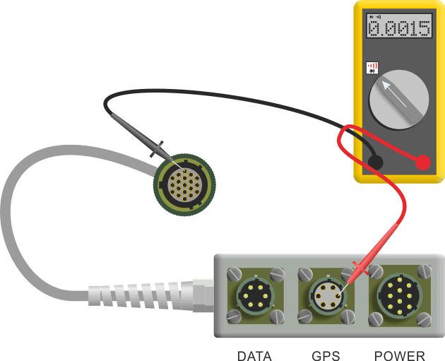
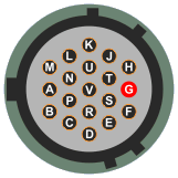
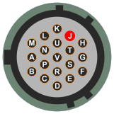
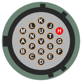
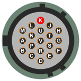
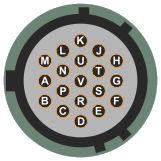
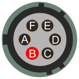
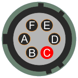
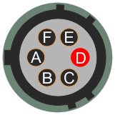
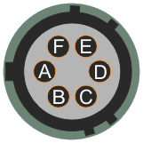
The pin-outs are given below: it is important to check for continuity on each of the relevant connections and also to ensure that there are no short-circuits from any pin to any other. (The complete pin-outs for every connector on the break-out box are given in the 6TD manual.)
| Function | Pin on 19-way connector 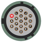
|
Pin on 6-way GPS connector 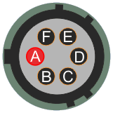
|
|---|---|---|
| Isolated ground | M | A |
| Power supply to receiver (+5 V DC) | G | F |
| NMEA data-stream from receiver | J | B |
| RS232 to receiver | H | C |
| One pulse per second (PPS) from receiver | K | D |
Further reading
- Global Navigation Satellite Systems (GNSS) overview
- A simple explanation of how GNSS works
- GPS (formerly Navstar) - the US' GNSS constellation
- The GPS home page
- GLONASS - the Russian GNSS constellation
- - the GLONASS home page (archived)
- BeiDou - the Chinese GNSS constellation
- - the BeiDou home page
- Galileo - the upcoming EU constellation
- - the Galileo home page
- NMEA overview
- A rich description of GNSS-related NMEA sentences
- The GPS week-number roll-over problem and how it affects Güralp products
- The GPS leap-second problem and how it affects Güralp products