Configuring a Fortimus for low-latency SEEDlink
SEEDlinkSEEDlink is a seismic data transmission protocol developed by IRIS. For a full description and the formal specification, please see IRIS's SEEDlink page. is a packet-based protocol. Data are assembled into packets before transmission and this, inevitably, increases the data latencyLatency is a measure of the time delay between a seismic signal being digitised and the digitised value being delivered to a data consumer. It is a key parameter for Earthquake Early-Warning systems. . If, for example, a 100 sps data-stream is divided into packets, each contains one hundred samples, the oldest sample in the packet will be held for a whole second before the packet can be delivered.
For minimum latency, a streaming protocol such as GDI-linkGDI-link is an ultra-low-latency streaming protocol for seismic data. For more information, please see the GDI-link protocol definition. is always recommended. Many existing applications, however, only accept data over SEEDlink so this document describes how to configure a Fortimus (or Fortis/Minimus combination) for the lowest possible SEEDlink latency.
Channels configuration
Seismological digitisers normally perform an initial data sampling at a very high rate; typically well over one hundred thousand samples-per-second. These data are then repeatedly down-sampled in a process known as decimation. To avoid aliasingIn digital signal processing, aliasing is the creation of unwanted signals that occurs when a signal containing frequencies higher than half the sample rate is sampled. See Wikipedia's 'Aliasing' page for more information. , the sample data must be digitally filtered to remove high frequencies before each down-sampling stage. This is known as the decimation filter chain.
Digital filters can be divided into two types: causal and acausal. Causal filters consider the value of many preceding samples when calculating the output value at any moment. They can produce a near-instantaneous output. In contrast, acausal filters also consider future sample values when calculating an output value. This means waiting until all the required future sample values have arrived before the output value can be produced, causing an unavoidable time-delay between the input and the output of such a filter.
Seismologists normally prefer acausal filters because they provide a more accurate transcription of the data. Causal filters distort the phase of incoming signals, changing the shape of the wave-front. However: acausal filters can cause several seconds of additional latency, which can be of critical importance in EEW applications. The default filters on the Fortimus and Minimus are acausal. This section describes how to enable causal filtering for low-latency operation.
Causal filtering is the default for the channels described as "low-latency" in the web page and documentation. This section describes how to disable the normal channels (which use acausal filters) and enable the low-latency channels, which use causal filters. The terms "causal" and "low-latency" are used interchangeably in the discussion below.
Causal filtering can be enabled either using the web interface or by editing the configuration file. Both techniques are described here:
- Jump to "Configuring causal filtering using the web interface"
- Jump to "Configuring causal filtering by editing the configuration file"
Configuring causal filtering using the web interface
Right-click on the Fortimus in Discovery's main page and select or from the context menu:
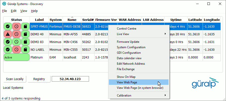
When the web page appears, select the tab:
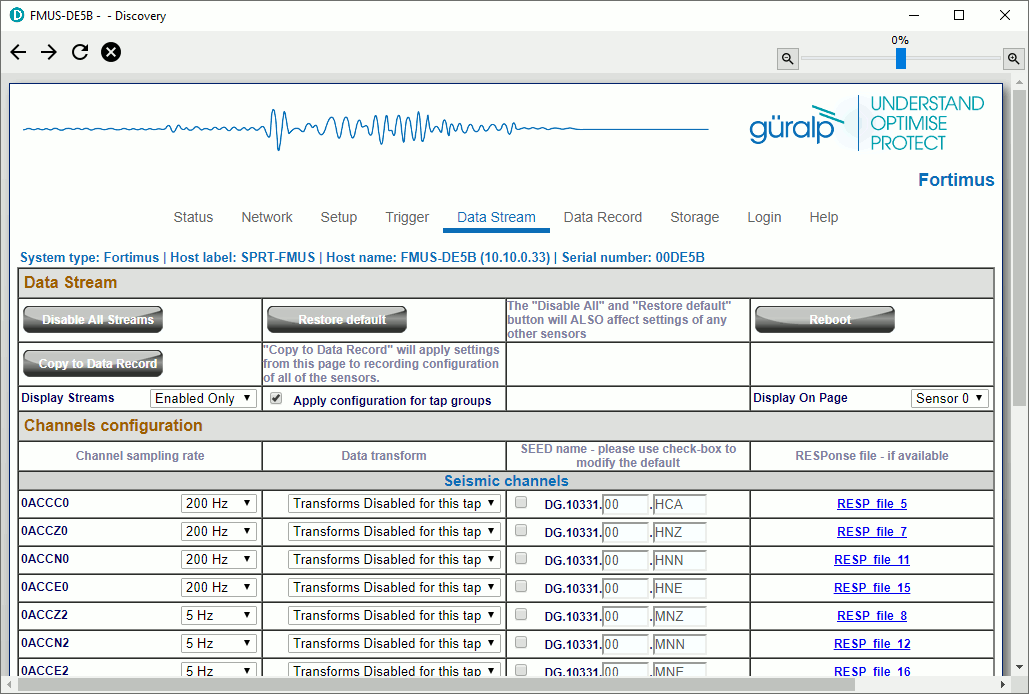
Click ![]() and then scroll down and tick the check-boxes for the three low-latency (causal) seismic
channels, , and
. These are distinguished by channel codes
ending in C. For good results, set the sample rate to
200 samples per second, unless you specifically need a different rate.
and then scroll down and tick the check-boxes for the three low-latency (causal) seismic
channels, , and
. These are distinguished by channel codes
ending in C. For good results, set the sample rate to
200 samples per second, unless you specifically need a different rate.
Next, select the tab of the web page:
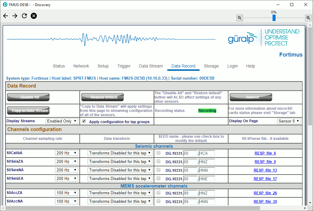
As before, click
![]() and then scroll down and enable the three causal channels for recording, using
the same sample rate that you specified in the
tab. Change the SEED channel location
code for these three steams to match that used in the
tab. In addition, enable recording for
the three acausal seismic channels, 0ACCZ0,
0ACCN0 and 0ACCE0. These
have channel codes ending in 0.
and then scroll down and enable the three causal channels for recording, using
the same sample rate that you specified in the
tab. Change the SEED channel location
code for these three steams to match that used in the
tab. In addition, enable recording for
the three acausal seismic channels, 0ACCZ0,
0ACCN0 and 0ACCE0. These
have channel codes ending in 0.
Once you have made the required changes, click
![]() to restart the digitiser with the new settings.
to restart the digitiser with the new settings.
This completes the channel configuration. Jump to the next section to configure the SEEDlink server.
Configuring causal filtering by editing the configuration file
An alternative way to configure the channels for causal operation is to download the configuration file, edit it and then upload it again.
To download a configuration file, right-click on the system in Discovery's main window and select :
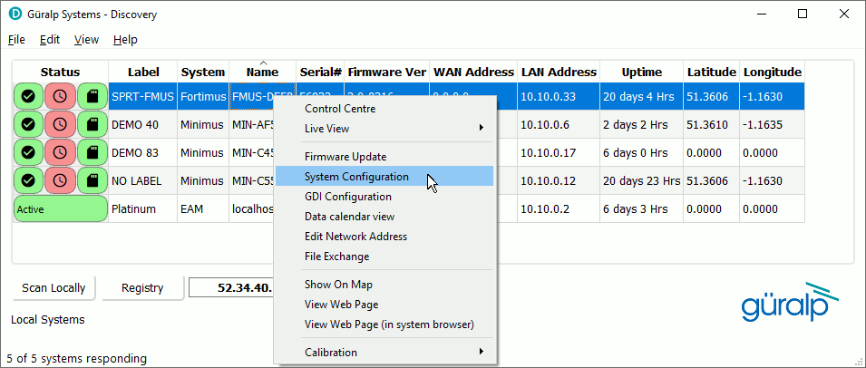
The System Configuration Import/Export Tool opens:
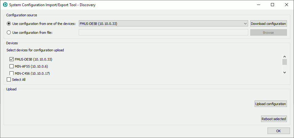
Check that the correct configuration source is selected and then click
![]() .
This downloads a human-readable text-file which you can then edit with a text
editor such as
Notepad++Notepad++ is a free (both as in “free speech” and
also as in “free beer”) and highly-recommended text-editor, source-code
editor and Notepad replacement that supports
several languages. It can be downloaded from
The Notepad++ web site.
.
This downloads a human-readable text-file which you can then edit with a text
editor such as
Notepad++Notepad++ is a free (both as in “free speech” and
also as in “free beer”) and highly-recommended text-editor, source-code
editor and Notepad replacement that supports
several languages. It can be downloaded from
The Notepad++ web site.
A sample file is presented below. Irrelevant entries have been removed: this causes no problems when the file is uploaded because, while any entries found are used to update the configuration, missing entries cause no action to be taken, preserving the previous settings. All values are 16-bit hexadecimal constants except where indicated.
Once the file has been edited, it can be uploaded again using the
System Configuration Import/Export Tool. Open the
tool as before, select the
Use configuration from file:
radio-button and then click
![]() to browse your file-system and locate the edited copy of the configuration
file. Alternatively, type the full path to the file into the box.
to browse your file-system and locate the edited copy of the configuration
file. Alternatively, type the full path to the file into the box.
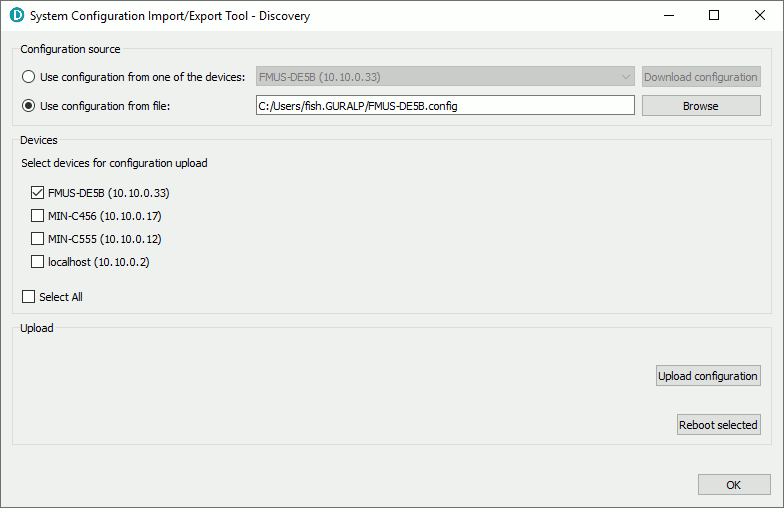
Select the system(s) that you wish to update using the check-boxes at the
left of the display and then click
![]() .
Once the upload is complete, click
.
Once the upload is complete, click
![]() to restart the digitiser(s) so that the new configuration takes effect.
to restart the digitiser(s) so that the new configuration takes effect.
This completes the channel configuration. Continue to configure the SEEDlink server, as desribed in the following section.
SEEDlink server network latency configuration.
The SEEDlink configuration options are explained in section §7.11.3 of the Fortimus manual. The following options are relevant to this discussion:
-
– this setting defines how often a SeedLink packet is assembled and transmitted to the client. Lower values mean lower latency but a value that is too low may cause packets to be partially empty: this can affect the backfill capabilities of the link and will certainly increase the network usage.
-
– this setting defines what size of SEEDlink packet should be used for data transmission. The choices are 256 or 512 Bytes. Note that:
- A data record size of 256 bytes is rarely supported by SEEDlink clients. Using 256-byte records can affect backfill capabilities.
- A data record size of 512 bytes may cause packets to be partially empty with, again, a negative impact on backfill capability and network load.
Some experimentation might be required to find the best balance between these competing objectives.
The following information may be useful when choosing values:
- A 256-byte data record can hold between 48 (uncompressed data) and 301 (fully compressed) samples.
- A 512-byte data record can hold between 112 (uncompressed data) and 721 (fully compressed) samples.
Example
If the low-latency (causal) channels are set to 100 samples per second, the following settings would result in the most efficient packetisation:
- For a data record size of 256 bytes, set to 4 deciseconds (0.4 of a second) so that, in the worst case scenario, when the data have to be sent uncompressed, the packet will contain 40 samples. (Space for a further 8 samples will be allocated in the packet but they will not be populated.) If the data can be fully compressed, the packet will still contain 40 samples but, in this case, space for 261 samples will be transmitted unpopulated.
- For a data record size of 512 bytes, set to 10 deciseconds (one packet each second) so that, in the worst case, when the data cannot be compressed, each packet will contain 100 samples (with 12 samples transmitted unpopulated). With fully compressed data, each packet will contain will still contain 100 samples but space for 621 samples will be transmitted empty.
If the lowest possible latency is paramount and we can ignore both network load and backfill capabilities, simply set to 1 decisecond. With 100 samples per second data, each packet will contain 10 samples but most packets will be transmitted empty.
The SEEDlink server can be configured either using the web interface or by editing the configuration file. Both techniques are described here:
- Jump to "Configuring the SEEDlink server using the web interface"
- Jump to "Configuring the SEEDlink server by editing the configuration file"
Configuring the SEEDlink server using the web interface
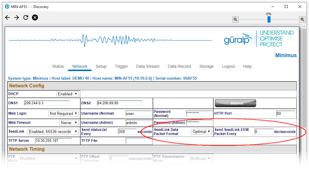
Before attempting to configure the SEEDlink server, select the link at the top of the web page
and log in as an administrator.
Once logged in, navigate to tab. The SEEDlink configuration parameters discussed above can be found at the bottom of the section:
Once you have made the required changes, click
![]() to restart the digitiser with the new settings.
to restart the digitiser with the new settings.
This completes the SEEDlink server configuration.
Configuring the SEEDlink server by editing the configuration file
An alternative way to configure the SEEDlink server is to download the configuration file, edit it and then upload it again. This process is described in detail in the instructions above. For low-latency SEEDlink server configuration, only two entries are relevant. Both are eight-bit values specified in hexadecimal. The Data Record Size parameter is encoded as follows:
- 0x01 – 512-byte records
- 0x02 – 256-byte records
The relevant entries are:
This completes the SEEDlink server configuration.