Chapter 2. Introduction
The 5TB borehole accelerometer is a three-axis strong-motion force-feedback instrument in a cylindrical sonde. The sensor system is self-contained except for its 12 – 30 V power supply, which can be provided through the same cable as the analogue data. An internal DC–DC converter ensures that the sensor is completely isolated.
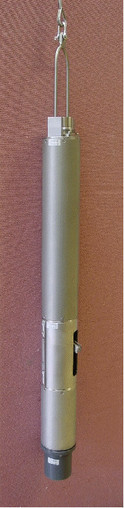 The sensor housing is manufactured from stainless steel, with double “O” rings throughout to ensure that the package is completely waterproof. A lifting hook on top of the sensor housing allows you to lower the sensor package into a borehole. To communicate with the sensor, a Güralp Systems 32-pin waterproof connector can be used (see the Appendices for pin-outs).
The 5T system combines low-noise components with high feedback loop gain to provide a linear, precision transducer with a very large dynamic range. In order to exploit the whole dynamic range two separate outputs are provided, with high and low gain. Nominally the high gain outputs are set to output a signal 10 times stronger than the low gain outputs. Both low and high gain outputs are differential, with a nominal impedance of 47 Ω; a single ground line is used for all signals.
Full-scale low-gain sensitivity is available from 4.0 g down to 0.1 g. The most common configuration is for the 5T unit to output 5 V single-ended output for 1 g (≈ 9.81 ms-2) input acceleration. The standard frequency pass band is flat to acceleration from DC to 100 Hz (although other low pass corners from 50 Hz to 100 Hz can be ordered.) A high frequency option provides flat response from DC to 200 Hz.
Each seismometer is delivered with a detailed calibration sheet showing its serial number, measured frequency response in both the long period and the short period sections of the seismic spectrum, sensor DC calibration levels, and the transfer function in poles/zeros notation.
Optionally, you can use a Güralp Hand-held Control Unit (HCU) and breakout box to distribute power and calibration signals to the sensor, and to receive the signals it produces. The HCU can also adjust DC offsets during installation, if required. It is available in both hand-held and rack-mounted formats.
2.1 Digital borehole installations
The Güralp DM24 digitizer is available in a borehole sonde form. Connecting a Güralp borehole instrument to a down-hole digitizer allows you to construct a true digital borehole installation. This has several advantages over a traditional borehole set-up:
Digital signals are not subject to attenuation as they travel up to the surface, so signals received are stronger and more reliable.
Digitizing the data at source allows you to ensure that its origin can be reliably traced.
The DM24 digitizer may also be combined with an Authentication Module within the borehole sonde, allowing you to generate cryptographically-signed data at the point of origin.
A digital borehole installation can be provided with RS232, RS422 or fibre-optic links to the surface, depending on the depth of the borehole.
When a down-hole digitizer is present, it takes the place of the strain relief unit in the borehole. The surface unit also takes a slightly different form, with a serial connector allowing you to attach a modem or other communications link. In this type of installation, instead of using the surface unit to pass control signals to the sensor, all functions can be accessed remotely via the digitizer.
If you prefer to install a stand-alone digitizer at the surface, it should be connected to the 19-pin RECORDER socket of the breakout box.
2.2 The hole lock system
The hole lock clamp unit in a 5TB instrument provides a stable platform for the sensor modules mounted above and below it. It is designed to maintain a positive pressure on the borehole casing over a prolonged period of time without attention, and to fix the sonde in place whilst avoiding transmitting any stresses.
Güralp Systems hole locks are constructed to order from accurate measurements of your borehole at the depth you wish to install the instrument.
In installations with sand backfill, or where the instrument rests on the bottom of the borehole, a hole lock may be unnecessary.
2.2.1 The single-jaw hole lock
The single jaw hole lock is the standard option for triaxial borehole instruments. It consists of an active clamp arm and a number of skids or studs on the sonde body. The arm is attached to a compression spring, which forces it to swing out from the sonde and wedge the body against the borehole wall. A serrated steel jaw at the end of the arm provides maximum grip against the borehole casing. The skids or studs and the locking arm together form a multi-point clamp, which aligns the sonde body parallel to the axis of the borehole and holds it firmly in place so that it cannot twist or slip under the influence of ground vibrations.
There are several configurations of skids and studs which can provide a suitable clamp. Either
the locking jaw pushes two steel skids against the side of the borehole, providing two line contacts;
only the tips of the skids come into contact with the borehole, providing three point contacts;
a single skid is combined with a pad to provide one line and one point contact; or
three studs provide three point contacts.
Studs have the advantage of being smaller than skids, but the contact points are very close to each other. You should evaluate the various locking methods available to see which works best in your borehole.
The spring inside the lock provides around 30 kg of force at its locking position. A DC actuator retracts the arm into the body of the lock so that the sensor mechanism can be installed and removed. The actuator consists of a DC motor with a planetary reduction gear-head, which drives the nut of a ball lead screw through the helical drive gears. The thread of the lead screw is prevented from turning, and so moves linearly when the nut turns.
The motor has a power system separate from that of the sensor, and can be controlled from the surface using a hole lock control unit. Once the sonde is installed, the hole lock control unit may be removed. Without power, the hole lock will not be able to retract, and the sensor will be secured.