Chapter 5. Calibration
All Güralp instruments are supplied with comprehensive calibration documents, and it should not normally be necessary to calibrate them yourself. However, you may need to check that the response and output signal levels of the sensor are consistent with the values given in the calibration document.
5.1 Absolute calibration
The sensor's response (in V/ms-2) is measured at the production stage by tilting the sensor through 90 ° and measuring the acceleration due to gravity. Local g at the Güralp Systems production facility is known to an accuracy of five digits. In addition, sensors are subjected to the “wagon wheel” test, where they are slowly rotated about their sensitive axes.
The response of the sensor traces out a sinusoid over time, which is calibrated at the factory to range smoothly from 1 g to –1 g without clipping.
5.2 Relative calibration
In addition to the response of the sensor, several other variables are calibrated at the production stage. Using these values, you can convert directly from voltage (or counts as measured in Scream!) to acceleration values and back. You can check any of these values by performing calibration experiments.
Güralp sensors and digitizers are calibrated as follows:
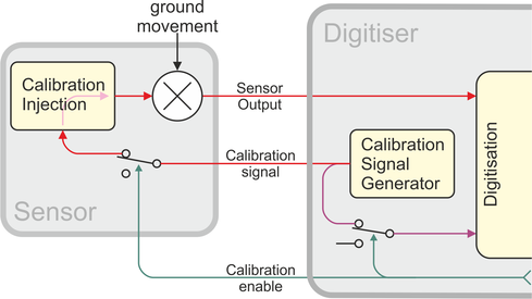
In this diagram a Güralp digitizer is being used to inject a calibration signal into the sensor. This can be either a sine wave or step function, depending on your requirements. As well as going into the sensor, the calibration signal is returned to the digitizer on a dedicated channel. (The channel is available for other uses when the instrument is not being calibrated.) The calibration signals and sensor output all travel down the same cable from the sensor to an analogue input port on the digitizer.
The signal injected into the sensor gives rise to an equivalent acceleration (EA on the above diagram) which is added to the measured acceleration to provide the sensor output. Because the injection circuitry can be a source of noise, a Calibration enable line from the digitizer is provided which can disconnect the calibration circuit when it is not required. Depending on the factory settings, the Calibration enable line must be held either high (+5 to +10 V) or low during calibration: this is given on the sensor's calibration sheet.
The equivalent acceleration corresponding to 1 V of signal at the calibration input is measured at the factory, and can be found on the sensor calibration sheet. The calibration sheet for the digitizer documents the number of counts corresponding to 1 V of signal at each input port. The sensor transmits the signal differentially, over two separate lines, and the digitizer subtracts one from the other to improve the signal-to-noise ratio by increasing common mode rejection. As a result of this, the sensor output should be halved to give the true acceleration.
All sensors are tuned at the factory to produce 1 V of output for 1 V input on the calibration channel. For example, a sensor with an acceleration response of 0.25 V/ms-2 should produce 1 V output given a 1 V calibration signal, corresponding to 1/0.25 = 4 ms-2 = 0.408 g of equivalent acceleration.
5.3 Using a DM24 series digitizer for calibration
You can gain maximum functionality from the 5TB by combining it with Güralp Systems' DM24 series digitizers and computers running Scream! software. Both of these allow direct configuration and control of any attached Güralp instruments. For full information on how to use a DM24 series digitizer, please see its own documentation. If you are using a third-party digitizer, you can still calibrate the instrument as long as you activate the Calibration enable line correctly and supply the correct voltages.
The calibration process for a 5TB using a DM24 and Scream is described in detail on our website. See the "How do I calibrate using a broadband noise source?" article in the Support→FAQs section of our web site.