Chapter 3. Principles of Operation
The Certis is a broadband force-feedback seismometer. Each of the three components consists of an inertial mass suspended on a friction-free pivot in such a way that it can only move in one direction – a single degree of freedom.
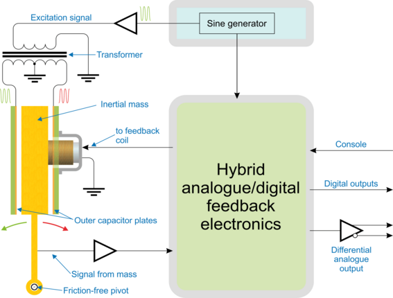
The mass is located between two capacitor plates, energised with anti-phase sinusoidal signals. The mass thus acts as the centre-plate of a three-terminal, variable capacitor so, if the mass is not central, a signal appears on it. The phase of this signal indicates the direction of displacement and the amplitude is proportional to the deviation from the central position.
The signal from the mass passes through a hybrid analogue/digital P.I.D. controller. The differential (D) component of the controller is implemented in the analogue domain while the proportional (P) and integral (I) components are realised digitally. The two resulting correction signals are summed via Rf and Cf and fed to a coil mounted on the mass. This surrounds a permanent magnet fixed to the instrument so that the combination forms an electromagnet which acts to drive the mass back to its centre position. A simplified block-diagram is shown below.
A chain of linear, proportional relationships connect the acceleration experienced by the instrument with the current flowing through the coil:
The capacitor plates and pivot are connected to the instrument so, to keep the mass central, the feedback system must impart an acceleration to the mass which is equal to that experienced by the instrument.
The mass is constant so, by F=ma, this acceleration is proportional to the force applied.
The coil geometry and the magnetic field in which it moves are both constant, so the force on the mass is proportional to the current through the coil.
In this way, the system produces a signal which is proportional to the acceleration experienced by the instrument. A signal proportional to velocity is present at the output of the forward-path compensation circuity and this is made available as the analogue output. Since it is also fed to an ADC, a digital output is also available.
3.1 Velocity and mass-position outputs
The Certis produces six main output signals: one each proportional to velocity in the three directions vertical (Z), North/South (N) and East/West (E) and, when connected to a Minimus in digital mode (see section 3.2), an additional three known as the “mass position” outputs: one corresponding to each of those directions.
Although referred to almost universally as “mass position outputs”, this second set of outputs do not actually correspond to the physical position of the masses. Instead, they are proportional to the force being applied to keep the mass central, averaged over the time period corresponding to the low-frequency cut-off point of the velocity outputs. Ideally, this should be as close to zero as possible, in order to maximise the output before clipping and minimise the power consumption.
Traditional force-feedback seismometers required the operator to monitor the mass position outputs at regular intervals and to take corrective action, known as nulling or centring, if any of them deviated too far from zero. This is not necessary with the Certis: the built-in microprocessor monitors the mass positions at all time and applies automatic correction when required. This technique enables the instrument to be operated at any angle up to 90° from the vertical.
3.2 Analogue and/or digital outputs
The Certis’ analogue outputs allow it to be used with a wide range of seismic digitisers. Once connected to a suitable DC power source, it will start operating and producing six analogue outputs: three proportional to velocity in the three directions and three corresponding mass position outputs.
The analogue velocity outputs are transmitted differentially. This means that a second, inverted copy of the signal is transmitted alongside the original. A differential input subtracts the inverted copy from the original, yielding a signal twice as strong and, in the process, cancelling out any noise picked up by the cable.
The analogue mass position outputs are not transmitted in this way because they only contain low-frequencies so any line noise can be filtered out after reception.
Each output carries a signal which varies between ±10 V, measured relative to ground – i.e. 20 V peak-to-peak. Each differential output consists of two such signals of opposite polarity, transmitted on different wires, so the difference between them varies between ±20 V. This is sometimes referred to as 40 V peak-to-peak.
When paired with a Güralp Minimus, Minimus+ or Minimus2 digitiser, however, a digital output can be enabled – either in addition to the analogue output or as an alternative. The digital output allows error-free transmission of the velocity data and additional environmental channels as well as identification, calibration and state-of-health information from the instrument. This greatly simplifies the administrative burden of setting up a station or network.
For more information, please see section 4.2.2.
3.3 Additional outputs
The Certis’ digital outputs include, in addition to the main velocity outputs,
Three mass-position outputs
The calibration signal return (see section 8.3)
Three MEMS accelerometer outputs
A magnetometer with a heading output
A thermometer
A barometer
A relative hygrometer
PLL parameters: phase, control and quality
For details of output channel names, see section 8.2.
3.4 Polarity of output signals
The front of the instrument is identified by an arrow on the lid. (The engraved words Güralp Certis are on the back, or South face of the instrument.) Wherever possible, the instrument should be placed on a level surface with the front pointing to geographical or magnetic North, as desired. Once so positioned:
If the instrument is moving upwards, the Z (vertical) output will produce a positive signal.
If the instrument is moving to the North, the N (North/South) output will produce a positive signal.
If the instrument is moving to the East, the E (East/West) output will produce a positive signal.
The internal MEMS accelerometer produces outputs with the same polarity with respect to acceleration (regardless of the direction of velocity), so
If the instrument experiences positive acceleration upwards, the Z (vertical) MEMS output will produce a positive signal.
If the instrument experiences positive acceleration to the North, the N (North/South) MEMS output will produce a positive signal.
If the instrument experiences positive acceleration to the East, the E (East/West) MEMS output will produce a positive signal.
Note: The internal MEMS accelerometer output is not compensated for the expected acceleration due to gravity when normally orientated. This means that, when the instrument is stood upright, the Z-component output of the MEMS accelerometer will indicate +1 g.