Chapter 4. Getting Started
4.1 Configuration Overview
Note: The Certis can be used with any of the Minimus digitiser family – Minimus, Minimus+ or Minimus2 – using the same techniques. Throughout this manual, however, only the term “Minimus” is used, even though the instructions apply equally to any of the Minimus family.
The Certis can be configured in three ways:
When connected digitally to a Minimus, it can be configured using Güralp’s free Discovery software. This method is described in section 4.2.
When a Minimus is not available, the Minimus can be configured using its serial console via a terminal emulator. This method is described in section 4.3.
Some configuration options can be affected by hardware control lines exposed on the instrument’s connector. This method is described in section 4.4.
Configuration changes are stored within the Certis so, if the instrument is pre-configured using a Minimus and Discovery, it can then be used with a 3rd-party digitiser and the pre-set configuration will be retained.
4.2 Configuration using a Minimus and Discovery
4.2.1 Enabling digital connections
To connect digitally to a Minimus, the digitiser must first be configured for digital connections. To do this:
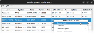
Open the Discovery application and locate the digitiser in the main list.
Right-click on the digitiser in the main list and select Control Centre from the context menu:
When the Control Centre window opens, click the Console icon in the left-hand tool bar.
When the Console window opens, place the cursor in the command box at the bottom and type the following:
resource add uartp6 96
Your screen should look like this:
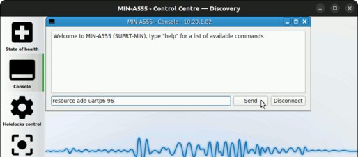
Click
 and the Minimus will respond with a short message:
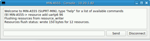
With the Certis connected to the Minimus, type
reboot
and click
again. This will power-cycle the digitiser. Click  to end the console session and close the Control Centre window.
When it has finished rebooting, the Minimus will communicate digitally with the Certis.
Note: Some values in the web interface, such as the Certis’ component sensitivities, are communicated from the instrument to the digitiser at power-up and might not appear immediately.
To configure the instrument, open the web interface of the Minimus and navigate to the Setup tab. Scroll down past the Digitiser Controls and Digitiser Config sections. The information and controls related to the Certis are grouped together in a section entitled Serial Sensor.
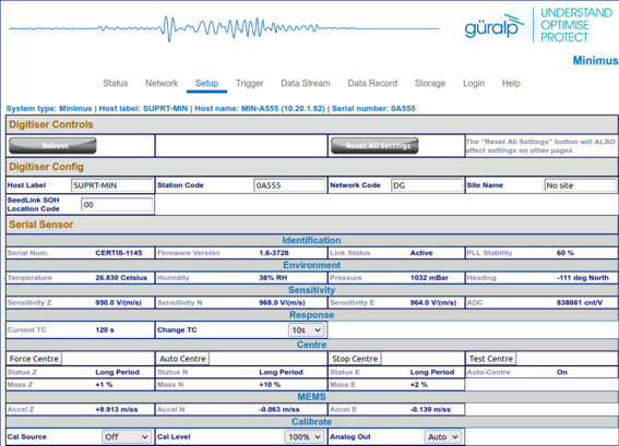
To configure the Certis using this screen, refer to the instructions in the following sections.
4.2.2 Selecting analogue or digital outputs
If your Certis is to be used with a digitiser from the Minimus family, you have the choice of analogue outputs, digital outputs or both.
If your Certis is to be used with a different digitiser – i.e. not a Minimus, Minimus+ or Minimus2 – only the analogue outputs are useful.
The Certis is shipped from the factory pre-configured in “auto” mode. This enables the digital output if a Minimus is detected and an analogue output otherwise.
Note: Güralp recommend the use of only digital outputs when the Certis is connected to a Minimus. This reduces the overall power consumption. The exception is Earthquake Early Warning systems where power is not an issue and the low-latency digitisation channels of the Minimus can be used to improve the response-time of the warning system.
4.2.2.1 Using only digital outputs
Digital outputs can only be used with digitisers from the Minimus family.
To enable the digital outputs, connect the Certis digitally to a Minimus as described in section 4.2.1. The digital outputs are always enabled when the Certis is connected like this but the analogue outputs can be disabled in order to save power.
To do this, open the web interface of the Minimus and navigate to the Setup tab. Scroll down to the Serial Sensor section. At the bottom right-hand-side of this section, in the Calibrate sub-section, set the Analogue out drop-down menu to Off or Auto.
Note: This field is not persistent and may not reflect the current configuration, so it must be changed at least once before setting it to the required value.
4.2.2.2 Using both digital and analogue outputs
Digital outputs can only be used with digitisers from the Minimus family.
To use both analogue and digital outputs simultaneously, connect the Certis digitally to a Minimus as described in section 4.2.1. Open the web interface of the Minimus and navigate to the Setup tab. Scroll down to the Serial Sensor section. At the bottom right-hand-side of this section, in the Calibrate sub-section, set the Analogue out drop-down menu to On.
Note: This field is not persistent and may not reflect the current configuration, so it must be changed at least once before setting it to the required value.
4.2.2.3 Using analogue outputs
Only analogue outputs are available when the Certis is used with a standard digitiser. The Certis is shipped from the factory in analogue mode so it can be connected immediately and used without configuration.
If the Certis has previously been used with a Minimus and has had its analogue outputs disabled, it is necessary to re-enable the analogue outputs. To do this, reconnect the Certis to a Minimus and set the Analogue out drop-down menu to On, as described in the previous section.
Note: This field is not persistent and may not reflect the current configuration, so it must be changed at least once before setting it to the required value.7
4.2.3 Adjusting the frequency response
The Certis has a frequency response which is flat to velocity between a configurable long-period corner and 100 Hz.
Note: The frequency response can only be adjusted when the Certis is connected digitally to a digitiser from the Minimus family but, once set, the setting is retained if the instrument is reconnected to a different digitiser.
To adjust the long-period corner, connect the Certis in digital mode to a Minimus, as described in section 4.2.1, open the web interface of the Minimus and navigate to the Setup tab. Scroll down to the Serial Sensor section.
The current response is shown in the Response sub-section as Current TC.
The adjacent drop-down menu can be set to any of 10, 20, 30, 45, 60, 90, 100 and 120 seconds. Select the desired long-period corner and wait for a few seconds for the instrument to adjust. The Current TC value will change to show the new response once the process is complete.
Note: The RESP files available from the Data Stream and Data Record tabs of the web interface will not change until the Minimus has been re-booted.
4.2.4 Setting the sample rate
The sample rates for streaming outputs and for recorded data are set independently: those for streaming outputs are configured via the Data Stream tab and those for recorded data are configured via the Data Record tab of the Minimus’ web interface. Each channel on these two tabs has an associated drop-down menu which presents a wide choice of sample rates along with an option to disable the channel.
Note: Each of these tabs has a drop-down menu called Display Streams, located just above the Channels configuration section. It offers the choice of Enabled only, Disabled only and All. If the channels that you wish to configure do not appear in the table below, set this control to All or Disabled only, configure the desired sample rates for the missing channels and then set this control back to Enabled Only.
Since it is normal for all three components from a triaxial instrument to be sampled at the same rate(s), the configuration tabs include a check-box labelled Apply configuration for tap groups, located just above the Channels configuration section. When ticked, changing the sample rate for one component will automatically change the sample rates for the other two components to match. When the check-box is clear, all sample-rates can be set independently of each other.
Note: Changing the sample-rate of a channel requires the Minimus to be rebooted before the change takes effect, although several such changes may be made consecutively without intervening reboots. The words Reboot Required appear in red italics at the top right of the web interface when such changes have been made but not enacted.
4.2.4.1 Digital outputs
When connected digitally, the digital outputs of a Certis can be streamed and/or saved to the Minimus’ SD card:
On the Data Stream tab of the Minimus’ web interface, the Certis’ digital channels appear as:
Vertical | North/South | East/West | |
Velocity channels | CertisZ0_ | CertisN0_ | CertisE0_ |
Mass position channels | CertisMassZ_ | CertisMassN_ | CertisMassE_ |
On the Data Record tab of the Minimus’ web interface, the Certis’ digital channels appear as:
Vertical | North/South | East/West | |
Velocity channels | CertisZ0_sd | CertisN0_sd | CertisE0_sd |
Mass position channels | CertisMassZ_sd | CertisMassN_sd | CertisMassE_sd |
4.2.4.2 Analogue outputs
On the Data Stream tab of the Minimus’ web interface, the Certis’ analogue channels, if enabled, appear as:
Vertical | North/South | East/West | |
Higher-rate velocity channels | 0ACCZ0 | 0ACCZ0 | 0ACCZ0 |
Lower-rate velocity channels | 0ACCZ2 | 0ACCZ2 | 0ACCZ2 |
Mass position channels | 0ACCM8 | 0ACCM9 | 0ACCMA |
On the Data Record tab of the Minimus’ web interface, the Certis’ analogue channels, if enabled, appear as:
Vertical | North/South | East/West | |
Higher-rate velocity channels | S0SeisZA | S0SeisNA | S0SeisEA |
Lower-rate velocity channels | S0SeisZB | S0SeisNB | S0SeisEB |
Mass position channels | S0IntZ | S0IntN | S0IntE |
4.2.4.3 Setting the gain
The sensitivity of the digital output of the Certis is factory set to 2.38 (nm s⁻¹)/count (i.e. 4.2×10⁸ counts/ms⁻¹) and cannot be changed. When the Certis’ analogue output is used with a Minimus digitiser, however, the input gain of the Minimus’ ADC can be set to one of Unity, ×2, ×4, ×8, ×12 or ×64. Combined with the Certis’ analogue sensitivity of 1000 V/ms⁻¹, these give the system the following sensitivities:
Minimus ADC gain | Overall Sensitivity |
Unity (×1) | 1000 counts / ms⁻¹ |
×2 | 2000 counts / ms⁻¹ |
×4 | 4000 counts / ms⁻¹ |
×8 | 8000 counts / ms⁻¹ |
×12 | 12000 counts / ms⁻¹ |
×64 | 64000 counts / ms⁻¹ |
4.3 Configuration via the serial console
The Certis can be configured via a serial console, accessible using the serial console cable. This can be connected to a PC running terminal emulation software.
Note: Güralp recommend the use of Picocom terminal emulation software on Linux PCs and PuTTY terminal emulation software on Windows PCs.
Configure your terminal emulation software to operate at 115200 Baud, 8-N-1 (one start bit, eight (8) data bits, no (N) parity bit, and one (1) stop bit) and disable all hardware and software flow control (i.e. no X-ON/X-OFF, RTS/CTS or DSR/DTR).
The available commands are described in the following sections.
4.3.1 Setting the frequency response
The long-period corner of the Certis’ frequency response can be set to any value between 10 seconds and 240 seconds. To set the corner period, enter the command
fbk save nnn
replacing nnn with the desired period in seconds. For example, the command
fbk save 30
will result in a frequency response which is flat to velocity between 30 seconds and 100 Hertz.
4.3.2 Controlling automatic-centring
The Certis can be configured for automatic centring with the command
mot auto
and automatic centring can be disabled with the command
mot stop
The mot command takes other arguments, as shown in the table below:
Command | Action |
mot auto | enable automatic centring |
mot stop | stop all centring operations and disable automatic centring |
mot status | show the current centring status |
mot recent 1 | initiate re-centring of the Z mass |
mot recent 2 | initiate re-centring of the N/S mass |
mot recent 4 | initiate re-centring of the E/W mass |
mot recent 7 | initiate re-centring of all masses |
mot idle 0 | force the Z channel into long period mode * |
mot idle 1 | force the E/W channel into long period mode * |
mot idle 2 | force the N/S channel into long period mode * |
mot test | run mechanical centring diagnostic program |
* Components undergoing centring are put into short-period mode in order to get rapid feedback about the response to centring motor movements. The idle commands place the specified components back into long-period mode.
4.3.3 Calibration commands
The cal command and its arguments are described in section 8.3.
4.4 Configuration using hardware control lines
The Certis has a number of hardware control lines exposed on its connector. See section 8.1.1 for the relevant pin numbers. The possible operations are described in the following sections.
4.4.1 Changing the frequency response
The Certis can be toggled between normal, long-period mode, where the long-period corner of the frequency response is as configured, and short-period mode, where the long-period corner of the frequency response is set to 20 seconds.
To change the mode between these two options, connect the Short Period mode pin to Logic / RS232 ground for eight seconds.
4.4.2 Controlling automatic centring
The Certis can be forced to recentre its masses at any time by connecting the Initiate Centring pin to Logic / RS232 ground for eight seconds.
Automatic centring can be disabled (and any current centring operation cancelled) by connecting both the Initiate Centring pin and the Short Period mode pin to Logic / RS232 ground for eight seconds.
4.4.3 Calibration
Calibration operations are described in section 8.3.
4.4.4 Busy status
The status of the centring subsystem can be displayed with an LED connected between the Busy pin and Logic / RS232 ground. The Busy pin provides a 3.3 V DC supply connected via a 200 Ω resistor so no additional components are required other than the LED.
Note: A standard 6.3 mm red LED has a Vf of around 1.7 V so the current will be (3.3-1.7)/200 = 8 mA and the power dissipated by the LED will be around 14 mW. A lower Vf will give a brighter light and vice-versa.
The LED will blink whenever the instrument is carrying out a centring operation.
When the LED is extinguished, the instrument is fully centred.