Chapter 3. Configuration and operation
3.1 Configuration
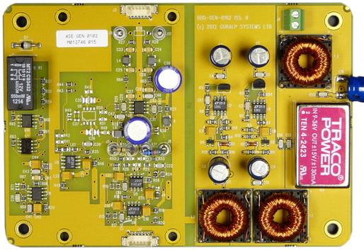
The input impedance of the Güralp ELP-0110 pre-amplifier provides damping for the sensor. The ELP-0110 can be supplied with any desired input impedance. If it is required subsequently to change the resistive component of the input impedance, this can be achieved by changing a single resistor. Access to this is gained by removing the lid of the unit, exposing the PCB.
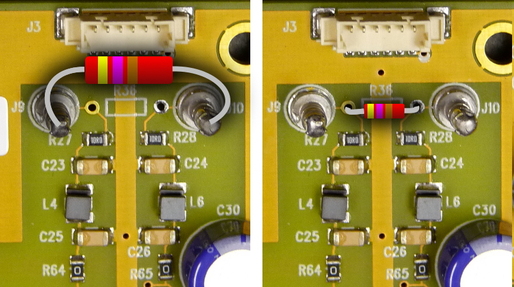
The PCB provides two solder turrets (terminal posts) and a location (marked R36) for a wire-ended (axial) resistor.
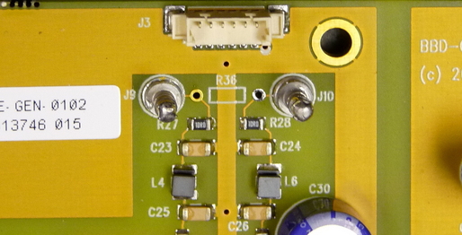
Either the turrets or the pads can be used, whichever is more convenient.
Since the sensor can be provided with several different coils and, optionally, a damping resistor pre-fitted, it is not practical here to give formulae for calculating the optimum value of the required resistance for any desired damping factor. If no resistor is fitted, the preamp presents an input impedance of 2 MΩ in parallel with 1.5 nF. The resistive component of the actual impedance will thus be 2 MΩ in parallel with any resistor fitted at R36.
3.2 Operation
The Güralp ELP-0110 pre-amplifier begins operating as soon as it is supplied with a DC power source of between 10 V and 36 V. This power is normally supplied by a connected Güralp DM24 digitiser.
Note: For best noise immunity, the pre-amplifier should be fitted as close to the instrument as possible.
3.3 Instrument calibration
The Güralp ELP-0110 pre-amplifier has a second channel to support the injection of a calibration signal, generated by the digitiser, into the calibration coil of the instrument. During normal operation, the output to the calibration coil is isolated from the pre-amplifier by an electromechanical relay.
The relay is controlled by the “Calibration enable” pin (pin R) on the digitiser connector (see section 4.2). This is an optically isolated “active high” input: during calibration, the digitiser provides +5V at this input with respect to “Logic ground”(pin Y). During normal operation, pin R is left unconnected.