The horizontal and vertical sensors are similar in design. The inertial mass in both cases consists of a transducer coil and a leaf-spring suspended boom which swings on a frictionless hinge. A triangular spring supports the weight of the mass; in the vertical sensor this spring is pre-stressed with a natural period of around 0.5 seconds, whilst the horizontal sensor has an unstressed flat spring with a natural period of around 1 second. Güralp 3T sensors have no spurious resonances below 140 Hz, and weigh around 180 g. The small boom size and stiff springs allow three independent instruments to be mounted within the casing, together with all the associated feedback electronics.
The 3T functions by monitoring the position of each mass with a capacitative position sensor. The three sensors are identical. Signals from the sensors are fed into an electronic processing unit, which is mounted in a screened compartment above the mechanical components (see below for details on the feedback circuitry.)
When the instrument is being transported, the masses are locked securely in their frames so as to relieve strain on the support hinges. This locking is performed by a small motor-driven clamp in response to a signal from the surface controller unit.
Before using the instrument, the boom of the vertical sensor must be levelled and the bases of the horizontal sensors tilted, so that the masses are centred in their equilibrium positions. These adjustments are made by small DC motors controlled remotely.
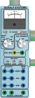
The signal voltages output by the 3T are proportional to ground velocity and are transmitted from the instrument on balanced differential lines. In addition, mass position signals are sent on single-ended lines, referred to analogue ground on the output plug. The 3T also receives control signals, which are used to lock (clamp) and unlock the masses and to run the motors which level and centre the instrument once in position. Finally, a line is provided for you to apply a calibrating voltage to the force transducers, thereby measuring the deflection sensitivity, along with three control lines which operate relays to isolate the feedback loops from the calibration signal input when not in use..
6.2 The control system
The internal operations of the 3T are supervised by a control microprocessor, which drives the mass clamping and centring adjustment motors. It responds to commands sent on three input lines, any of which is activated by connecting it to digital ground for seven seconds.
The signals you can send to the microprocessor are termed LOCK, UNLOCK, and CENTRE. Each command acts on the vertical, N/S and E/W masses in turn. The microprocessor prevents the system from attempting incompatible actions (e.g. centring when the masses are clamped).
While a command is taking place, if you are using a Break-out box or Hand-held Control Unit, its BUSY LED will flash; you can use this for diagnostic purposes. See the description of each command for full details.
When no command is active, i.e. all three lines are high, the control microprocessor goes into a power-saving mode. In routine operation, the lines are controlled from the breakout box, Hand-held Control Unit or digitiser. If you send control signals to the 3T manually, you must ensure that the lines are allowed to float high after sending the signal, or the equipment may be damaged. A “biased-OFF” type switch can be used for this purpose.
6.2.1 LOCK
This command locks the masses and clamps the horizontal sensors by tilting them up to their end stops.
In detail, the process acts as shown in the following graph. The top three streams are the mass position outputs of each component (Z, N/S and E/W, respectively), whilst the bottom one represents the state of the BUSY LED (up = on).
The five-stage process comprises locking the Z, N/S and E/W masses, followed by longer periods tilting the N/S and E/W sensor base to their end stops. During the latter two periods, the position of the N/S and E/W masses will “flip” to one side.
The BUSY LED is lit during each stage, but goes out briefly between stages, allowing you to follow the progress of the lock.
6.2.2 UNLOCK
This command unlocks the sensor masses and prepares the instrument to begin operating.
On earlier models, if UNLOCK is activated when the masses are already unlocked, the processor will lock them and attempt to unlock again. This is useful if you suspect that the locking procedure has failed. Later models are fitted with limit switches so this is no longer necessary.
Again, you can use the BUSY LED to monitor the progress of unlocking.
The instrument checks to see whether the Z, N/S and E/W masses are locked.
The instrument checks the N/S and E/W sensor bases.
The Z component is unlocked.
The N/S and E/W components are unlocked. These are quicker than the Z component.
(see graph below) The N/S sensor base is unlocked, followed by the E/W base. These processes take longer still.
After unlocking, the instrument automatically performs a round of centring (see below).
6.2.3 CENTRE
This command re-centres the masses. If the masses are clamped, or if the sensor mass positions do not exceed ± 1.2 V, the CENTRE command does nothing. Otherwise, it attempts to zero the output of the vertical, N/S and E/W sensors in sequence by exerting small extra forces on the boom. For the vertical sensor, a motor-driven adjuster presses a small spring lever against the boom until the mass position sensor indicates an offset close to zero. In the case of the horizontal sensors, the sensor frame is tilted on its base plate. Again, the controller monitors the mass position sensor and stops the centring process once it reaches its lowest offset.
This graph shows the entire process of unlocking and centring:
1 – 5. The unlocking process as described above.
The BUSY LED pulses to indicate that it is centring the Z component. The mass position output does not change for a while, as it is beyond the range of the output. However, after a few pulses, the position of the Z component comes within range and is centred. The pulses become more brief as this goes on, until a pulse is missed (signifying that no corrective impulse is needed.)
The N/S and E/W components follow in the same way, until all three masses are centred and the process completes. The first round of centring has to move the N/S and E/W components all the way from their end stops, whilst the Z component is often closer to the proper position. Because of this, the first Z centring operation takes much less time than the others, and you may not notice it.
After successful centring, the mass position outputs should be in the range 0.1 – 0.8 V. If the centring process leaves the mass position outputs above ±1.1 V, you should start another centring cycle by activating the CENTRE command again. You will probably need to initiate the centring process several times before the masses are adequately centred.
6.3 RS232 control interface
As an option, the 3T can be supplied with an RS232 control interface, which uses three additional pins on the sensor output connector.
The control electronics save power by switching off the sensor feedback electronics whilst the masses are locked. When you unlock the masses, either using the standard logic lines (see above) or over the RS232 interface, the control electronics automatically “wake up” the rest of the sensor.
To connect to the RS232 control interface, attach the sensor to a PC's serial port using the cable supplied, and use a terminal program such as minicom (on Linux) or PuTTY (on Windows) to connect to the port. Set the baud rate to 4800, with 8 data bits, no parity bit, 0 stop bits and no flow control.
Now power up the sensor. You should see the message PWR OK indicating that it is ready to receive commands. Each command is a single character. When you enter a command character, the controller will echo it back to your terminal so you can see it.
After around 10 seconds of inactivity, the control electronics will go into power-saving mode. You will need to wake up the controller by sending any character before you can issue commands. This character will not be interpreted as a command, and the controller will not echo it back to your terminal.
6.3.1 Help
Sending H causes the controller to reply with a short list of available commands.
[U]nlock [C]entre [L]ock [S]tatus [Q]uit [H]elp
6.3.2 Unlock
Sending U will start an unlock sequence, exactly as if you had activated the Unlock line on the output port. The sensor will automatically perform one round of centring after it has been unlocked, and the electronics will be fully activated.
If the unlocking process finishes normally, the controller will reply with OK. If there was a problem, such as one or more components failing to unlock or centre, the controller will report NG (“no good”.)
6.3.3 Lock
Sending L will start a lock sequence, as if you had activated the Lock line on the output port (including unlocking the sensor before locking, if necessary.) The sensor electronics will be placed in power saving mode as soon as the masses are successfully locked.
If the locking process finishes normally, the controller will reply with OK. If there was a problem, the controller will report NG.
6.3.4 Centre
Sending C will start a centring sequence, as if you had activated the Centre line on the output port. When the process finishes, the controller will reply with OK, or NG if there was a problem. You may need to issue the command several times before the masses are adequately centred.
If you try to centre the masses when they are locked, the controller will reply with OK immediately but take no action.
6.3.5 Status
Sending S causes the controller to reply with the current instantaneous mass positions, e.g.:
V: +5 N: +8 E: -10
The mass positions are measured by the controller's on-board ADC, which has a nominal range of ±127 counts. For accurate mass position information, you should use the analogue lines provided elsewhere on the output connector.
6.3.6 Quit
Sending Q ends your command session, and puts the controller into power-saving mode. To issue further commands, you will need to wake up the controller by sending any character. This character will not be treated as a command, and will not be echoed back to your terminal.
6.4 The feedback system
The output from a modern broadband seismometer does not depend on the natural characteristics of the instrument. Instead, the period and damping of the sensor is completely determined by a feedback loop which applies a force to the sensor mass opposing any motion. The force required to restrain the movement of the mass can then be used to measure the inertial force which it exerts as a result of ground motion.
All Güralp 3 series units are based on these general principles. The capacitative position sensor for each mass produces a voltage proportional to the displacement of the mass from its equilibrium position. After amplification, this voltage generates a current in the force transducer coil which tends to force the mass back toward equilibrium. The feedback loop has a sufficiently high gain to cancel the motion of the mass. Since the mass is not moving, the forces acting on it must be balanced; the feedback voltage then directly measures the force, and hence the acceleration, which is being applied to the mass. The feedback loop introduces a phase shift, which must be carefully controlled if the instrument is to remain stable over its entire frequency range. This is achieved using compensation components in the forward and feedback paths.
Force feedback seismometers of this type rely on the assumption that the force transducer produces a field of constant strength. The magnetic circuit and magnet/pole assembly in the 3T are designed so that the field strength from the feedback transducer is constant over large deflections and current levels. Independent tests have shown that the mechanical suspension system and electronics of a 3T instrument are linear to better than 107 dB (source: measurements made at ASL during evaluation for the USGS National Network.)
In a feedback seismometer with a displacement transducer, it is essential to monitor the acceleration output. This provides the position of the displacement transducer and therefore also the mass position, as the displacement transducer is attached to the sensor inertial mass. The sensor should always be operated with the displacement transducer centred or nulled, so that the response to input acceleration is linear.
There are two types of feedback system which can be used in a 3T instrument, known as hybrid and conventional-response feedback.
These are both described below.
6.4.1 Hybrid feedback
The hybrid feedback method of operation is illustrated by the following schematic diagram:
The hybrid feedback circuit contains a single capacitor in parallel with a resistor, resulting in a single dominant pole. Below this frequency, which can be varied from the standard 30 seconds, the response of the seismometer is flat to ground acceleration. Above it, the response is flat to velocity. Hybrid-feedback systems provide a stable response, particularly for portable systems, with a high saturation level at high frequencies and a high dynamic range at long periods.
An active low-pass filter provides a high-frequency cut-off point at a frequency you specify. Without the filter, the velocity response is flat up to 100 Hz. Outside the feedback loop there is an active high-pass filter with a corner frequency of 0.01 Hz (100 s) or 0.005 Hz (200 s), which serves to remove any DC offsets.
6.4.2 Conventional-response feedback
The conventional-response feedback system has an additional parallel feedback circuit, consisting of a non-inverting integrator in series with a resistor. This arrangement results in two poles at specified frequencies. The velocity response of a conventional-response system is defined by a transfer function identical to that of a conventional long-period sensor with a damping constant ζ of 0.707 (1/√2)
The seismometer can be supplied with an equivalent resonant frequency of 0.033 Hertz (30 seconds), 0.01 Hertz (100 seconds) or 0.0083 Hertz (120 seconds) as required. An active low-pass filter provides a high-frequency cut-off point at a frequency you specify.
6.4.3 Comparisons
The figures below plot the comparative response of a conventional velocity output broadband sensor and a hybrid output broadband sensor. The first graph shows the response in terms of output against input acceleration in units of V/ms-2, whilst the second is plotted in terms of output against input velocity, in V/ms-1.