Chapter 6. Connector pin-outs
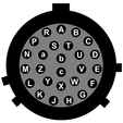
6.1 Output port and breakout box RECORDER connector
This is a standard 26-pin military specification bayonet plug, conforming to MIL‑DTL‑26482 (formerly MIL‑C‑26482). A typical part-number is 02E-16-26P although the initial “02E” varies with manufacturer. Suitable mating connectors have part-numbers like ***-16-26S and are available from Amphenol, ITT Cannon and other manufacturers. |
|
Pin assignments used when the High Gain option is not fitted:
Pin | Function | Pin | Function |
A | Velocity +ve, vertical ch. | P | Calibration signal (all channels) |
B | Velocity –ve, vertical ch. | R | Calibration enable (all channels) |
C | Velocity +ve, N/S ch. | S | Not connected |
D | Velocity –ve, N/S ch. | T | Not connected |
E | Velocity +ve, E/W ch. | U | One-second mode * |
F | Velocity –ve, E/W ch. | V | N/S centring motor * |
G | Mass position, vertical ch. | W | E/W centring motor * |
H | Not connected | X | Vertical centring motor * |
J | Mass position, N/S ch. | Y | Digital ground / Motor return * |
K | Not connected | Z | Not connected |
L | Mass position, E/W ch. | a | Not connected |
M | -12V DC (3-way power opt) | b | Power ground |
N | Signal ground | c | +12V DC supply |
* see notes on following page
| Wiring details for the compatible socket, ***-16-26S, as seen from the cable end. |
Note: In the standard instrument, pin U selects one-second mode when grounded to pin Y, which is digital ground.
In instruments with the remote nulling option fitted, pins V, W and X provide access to the motors diving the nulling potentiometers. Pin Y serves as the return for the motor currents.
In instruments with the digital nulling option fitted, grounding pin U for seven seconds initiates the automatic centring process.
These connectors are plug-compatible with the Güralp 3ESP, so you can use Güralp 3ESP hand-held control units and breakout boxes to monitor the low-gain velocity outputs and run calibrations. Pressing ENABLE and CENTRE on a Güralp 3ESP hand-held control unit activates pin U and switches the 40T into one-second mode for as long as the buttons are held down. You must do this before you can monitor mass position outputs, e.g. for offset nulling.
Note: 40T units with the optional additional high-gain outputs cannot be used with a Güralp 3ESP breakout box. The pin-outs for these sensors are given in the next section.
Pin R, Calibration enable, is equivalent to the vertical calibration enable line on a Güralp 3ESP, so you can calibrate all channels by setting up Scream! or a hand-held control unit to calibrate the vertical channel.
6.2 Output port and breakout box RECORDER connector (high-gain option)
These units use the same plug with the following pin assignments. High gain velocity outputs are denoted HGV.
This is a standard 26-pin military specification bayonet plug, conforming to MIL‑DTL‑26482 (formerly MIL‑C‑26482). A typical part-number is 02E-16-26P although the initial “02E” varies with manufacturer. Suitable mating connectors have part-numbers like ***-16-26S and are available from Amphenol, ITT Cannon and other manufacturers. |
|
Pin | Function | Pin | Function |
A | Velocity +ve, vertical ch. | P | Calibration signal (all ch) |
B | Velocity –ve, vertical ch. | R | Calibration enable (all ch) |
C | Velocity +ve, N/S ch. | S | HGV -ve, vertical channel |
D | Velocity –ve, N/S ch. | T | HGV +ve, vertical channel |
E | Velocity +ve, E/W ch. | U | Acc/Vel (or Centre - see P17) |
F | Velocity –ve, E/W ch. | V | N/S centring motor* |
G | Mass position, vertical ch. | W | E/W centring motor* |
H | HGV –ve, E/W channel | X | Vertical centring motor* |
J | Mass position, N/S ch. | Y | Motor return* |
K | HGV +ve, E/W channel | Z | HGV -ve, N/S channel |
L | Mass position, E/W ch. | a | HGV +ve, N/S channel |
M | -12V DC (3-way power opt) | b | Power ground |
N | Signal ground | c | +12V DC supply |
* see notes in section 6.1.
| Wiring details for the compatible socket, ***-16-26S, as seen from the cable end. |
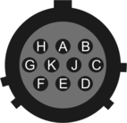
6.3 Breakout box power connector
This is a standard 10-pin military-specification bayonet plug, conforming to MIL‑DTL‑26482 (formerly MIL‑C‑26482). A typical part-number is 02E-12-10P although the initial “02E” varies with manufacturer. Suitable mating connectors have part-numbers like ***-12-10S and are available from Amphenol, ITT Cannon and other manufacturers. |
|
Pin | Function |
A | Power 0 V |
B | +12 V DC supply |
C | Not connected |
D | Not connected |
E | Not connected |
F | Not connected |
G | Not connected |
H | –12 V DC supply (3-way power option) |
J | Not connected |
K | Not connected |
| Wiring details for the compatible socket, ***-12-10S, as seen from the cable end. |