Chapter 5. Inside the 5T Compact
The 5T Compact unit is constructed of hard-anodised aluminium with “O” rings throughout, ensuring a completely waterproof housing.
Inside, the masses of the vertical and horizontal components are attached to the rigid frame with parallel leaf springs. The geometry of the spring spacing, together with the symmetrical design, ensures large cross-axis rejection. The sensor mass is centred between two capacitor plates and moves in a true straight line, with no swinging motion. Feedback coils are attached to either side of the sensor mass, forming a constant-flux, force-feedback transducer.
The vertical and horizontal sensors are identical in mechanical construction; the vertical sensor's mass spring system is adjusted to compensate for gravity. They are mounted directly onto the base above the feedback control board.
The signal and feedback circuits inside the 5T Compact accelerometer are arranged according to the following diagram:
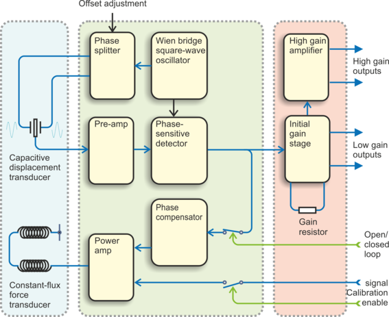
The mass and the capacitor plates are energised by a two-phase transformer driver, forming a differential capacitor. This acts as a capacitive transducer, whose signal is then demodulated with a phase-sensitive detector. The accelerometer feedback loop is completed with a phase compensator and a feedback force transducer power amp. A switchable input line allows the feedback loop to be broken, providing open-loop response when required.
The differential output amplifier scales the output sensor sensitivity and a second stage amplifier provides a further cascaded gain stage.
5.1 The force transducer
The 5T Compact is a force-feedback strong-motion accelerometer which uses a coil and magnet system to generate the restoring feedback force. Such accelerometers inherently depend on the production of a constant-strength field in the magnet gap. Although the high quality magnets used in the 5T Compact accelerometer are exceedingly stable under normal conditions, if the sensor is sited in an area where the background seismic noise is much higher than that of a vault constructed in a seismically stable location, the flux density may be affected by the external magnetic field generated by the feedback transducer coil.
In order to minimise non-linearities in the feedback force transducer, the 5T Compact uses a symmetrical system of two magnets and two force coils. Any increase in flux in one coil is cancelled by a corresponding decrease in flux in the other, thus eliminating any non-linearity due to lack of symmetry.
5.1.1 The sensor transfer function
Most users of seismometers find it convenient to consider the sensor as a “black box” which produces an output signal V from a measured input x. So long as the relationship between V and x is known, the details of the internal mechanics and electronics can be disregarded. This relationship, given in terms of the Laplace variable s, takes the form
( V / x ) (s) = G × A × H(s)
In this equation
G is the acceleration output sensitivity (gain constant) of the instrument. This relates the actual output to the measured input over the flat portion of the frequency response.
A is a constant which is evaluated so that A × H(s) is dimensionless and has a value of 1 over the flat portion of the frequency response. In practice, it is possible to design a system transfer function with a very wide-range flat frequency response.
The normalising constant A is calculated at a normalising frequency value fm = 1 Hz, with s = j fm, where j = √–1.
H(s) is the transfer function of the sensor, which can be expressed in factored form:
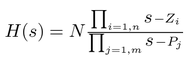
In this equation, zn are the roots of the numerator polynomial, giving the zeroes of the transfer function and pm are the roots of the denominator polynomial, giving the poles of the transfer function.
In the calibration pack, G is the sensitivity given for each component on the first page, whilst the roots zn and pm, together with the normalising factor A, are given in the Poles and zeroes table. The poles and zeroes given are measured directly at Güralp Systems' factory using a spectrum analyser. Transfer functions for the vertical and horizontal sensors may be provided separately.
5.2 Electrical connections
Each channel inside the 5T Compact sensor has four output lines: a pair of differential outputs with low gain and another pair with high (nominally 10 ×) gain.
The two pairs of output lines are balanced about signal ground so that either differential drive or single-ended drives of opposite polarity (phase) are available. For a single-ended drive, the signal ground must be used as the signal return path. You must not ground any of the active output lines, as this would allow damaging currents to flow through the output circuits. Also, if single-ended outputs are used, the positive acceleration outputs must be the ones interfaced to the recorder.
For distances up to 10 metres, you can connect the sensor outputs using balanced screened twin lines terminated with a high-impedance differential input amplifier. The sensor outputs have a nominal impedance of 47 Ω.
The 5T Compact is normally powered directly from a connected Güralp digitizer through its signal connector, although you can use a separate 10 – 36 V DC power supply if you wish. An isolated DC–DC converter installed inside the sensor housing forms the main part of the 5T's power supply; its filtered outputs provide the ±12 V required to operate the sensor electronics. The DC–DC converter is protected against polarity reversal. Optionally, this DC–DC converter can be omitted, in which case you will need to provide a ±12 V three-way power supply yourself.
The calibration signal and calibration enable inputs are referenced to the signal ground. If you are using a Güralp digitizer, these lines can be connected directly to its calibration lines. For “active high” instruments, you will need to provide a 5 V logic level, referenced to the signal ground. For “active low” instruments, you can connect these lines to the signal ground to activate the associated function. See Chapter 4, for more details.