Chapter 5. Pre-deployment operations
5.1 Battery charging
The charge status can be calculated by monitoring the current at the start, during, and at the end of charging charging.
Caution: During charging, the battery cells can release some gas which can build up inside the casing. Therefore, before charging, we advise to unscrew the ventilation screw located on the top of the battery canister. Please be aware that when this screw is open, no foreign material (e.g. fluid, dust, particles) should not enter this opening. We recommend, only opening this ventilation when the instrument is in a dry, dust-free and well-ventilated area.
Batteries should be charged according to the following steps:
Unscrew and remove the 4-pin cable SOL-CSA-GURA-0003 from the battery module, and replace with the similar cable that is attached to the battery charger.
Apply power to the IEC inlet at the rear of the battery charger unit and turn on using the switch at the rear of the charging unit.
Press the green “ON/OFF” switch at the front of the unit to switch the charging unit on, and the display will light up.
Press the black “START/STOP” button.
The display shows the charging profile where: I = current flowing into the battery pack (limited to 10 A maximum); V = charging voltage at the battery (limited to 9V maximum).
The sum total charge applied is shown in the mAh / Ah part of the display. This is a cumulative running total, so record the start value before starting a charge cycle.
Once the charge cycle has begun. The charge will begin in CC constant current mode with 10 A being delivered to the battery.
As battery reaches 80% charge, the current will reduce at the voltage will be limited to 9 V.
Once the current drops to 0.00 A, the battery is fully charged. At this point, record the charge in mAh or Ah and subtract the equivalent starting value (Step 6) to find the total charge that has been put into the batteries.
Typically, 300 Ah flows into the batteries that have been fully discharged and then charged, and up to 20 Ah flows into batteries that have not been used.
Caution: If you turn the charger off at the mains, with the battery connected and the green button is left in the “ON” switch, the display will remain lit up. The display will then slowly discharge the battery, so be careful of not leaving it in the mode for an extended period of time.
Fully charging each OBS unit will take approximately 30 hours to complete. To charge the OBS, you will need to plug it into the Deck Unit. The deck unit should also be plugged into a permanent power source.
When not charging on the vessel deck, the batteries will need to be vented during charging.
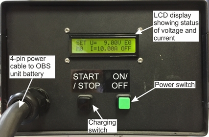
Front panel of the battery charging unit
5.2 Clock synchronisation
The Breve OBS has a temperature-compensated real-time clock which is used for time-stamping recorded data. The clock must be synchronised to GPS time before each deployment. When the system is retrieved at the end of the deployment, the internal clock should be compared to GPS time, and, if desired, a first-order linear correction can subsequently be applied to the time-stamps of the data to compensate for any drift.
1. Power-cycle the OBS Unit(s) and connect the unit(s) to the Deck Control Unit, switch on the Deck Control Unit and the computer, and open the Scream 4.5 software as described in Section 4. Do not connect the GPS to the Deck Control Unit at this point.
2. Within a few minutes, the connected instrument(s) appear in Scream under the COM** source trees. Each digitiser has an associated icon. These icons are colour-coded to show the status of the associated digitiser. The icons appear initially with both top and bottom clear ( ). This means that the OBS unit digitiser’s clock has not yet received any synchronisation information. Furthermore, by double-clicking on the ****00 stream (the timing status file), the status “NO GPS” is reported.
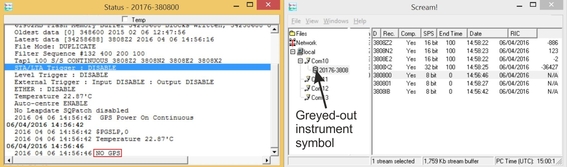
Scream main window and timing status file when the clock is not synchronised and the GPS antenna is not connected to the Deck Control Unit.
3. Now connect the GPS antenna and six-pin cable to the GPS port located at the top-right of the main panel of the Deck Control Unit. Ensure that the antenna has a clear view of the sky.
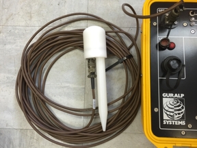
Connecting the GPS antenna to the Deck Control Unit.
4. Within a few minutes, the instrument symbol in the Scream main window should turn green ( ), and “Clock sync’d to GPS...” will be reported in the timing status file. This mean that the clock inside the digitiser is now synchronised and the GPS antenna is still connected, constantly trimming the internal clock.
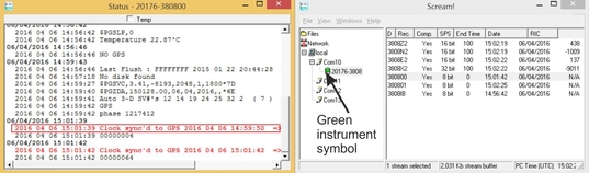
Scream main window and timing status file when the clock is synchronised and the GPS antenna is still connected to the Deck Control Unit.
5. Now the clock will fully trim. When this is complete, the instrument symbol will turn purple () and “TRIMMED” (when offset and drift become very small) will be reported in the status file. The user will not be able to deploy the instrument(s) until this has been achieved.
6. Now disconnect the GPS antenna and cable from the deck control unit. The instrument symbol will now turn yellow. “No GPS” will be reported in the timing status file, as well as drift and offset values appearing. These features indicate that there has been an interruption to the incoming timing information, but the internal clock is fully synchronised and no longer relying on the GPS timing source.
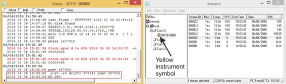 Scream main window and timing status file when the clock is synchronised and the GPS antenna is disconnected from the Deck Control Unit.
If the instrument is given a red symbol ( ) when the GPS is connected, the system has received no timing information for over an hour. This normally represents an error condition: contact Güralp Technical Support for advice. Otherwise, a red symbol is normal when the GPS is disconnected.
5.3 Huddle test
A huddle test using all instruments is required before deployment. Güralp recommends that a huddle test of at least 12 hours is conducted in the country of installation to identify the working order of the Breve OBS and all components work. A huddle test also helps the users become familiar with the operation of the equipment.
Orient and level each sensor so that each instrument is oriented in the same direction. This allows waveforms between to be visually correlated for recording consistency.
Power up the instruments and synchronise clocks (see Section #).
Carry out a drop/stamp test to produce a clear signal that can be identified on all instruments.
Evaluate the huddle test for any instrument anomalies. Verify the recorded time series and power spectral density plots (can be plotted using Güralp Scream! Software). Verify that the sensor data is time aligned between the stations. Verify consistent polarity between the sensors.
Perform a release test to test the acoustic release in air using the deck unit (See Sections 2.2.7, 2.5 & 6.4).
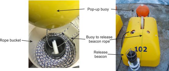
5.4 Arrangement of ropes
The Breve OBS comprises two main polyester ropes.
One rope is the max. 150 m long piece of rope neatly coiled around the black inner tube in the bucket beneath the pop-up buoy.
The other rope connects the pop-up buoy to the acoustic release beacon. This rope should be laid over the top of the Breve OBS frame, adjacent to the lifting hook, and run down the side of the acoustic release beacon (ensuring that it does not get snagged or caught along any sharp corners or joints and securely fastened to the release block with both arms fully closed.
For more details on the operation of the release beacon, the user is referred to the Quick Start Guide of the Applied Acoustics 1519 Release Beacon, REL-1519-8000-1_1519 (available from Guralp on request).