Chapter 2. Getting started
The following steps will enable you to connect and start using your CMG-CD24R8.
Connect your sensors (or other ±10V differential sources) to either the front-panel or rear-panel inputs. See section 5.1.1 for the front-panel input pin-outs and section 5.2.1 for the rear-panel input pin-outs.
If using a single CMG-CD24R8, connect your GPS receiver to the GPS input on the rear panel. This connector provides power to the GPS receiver and accepts NMEA and PPS inputs from the receiver to provide synchronisation.
If using multiple CMG-CD24R8s, connect your GPS receiver to the GPS input on the rear panel of the first digitiser. Connect a GPS “daisy-chain” cable (part number CAS-PEP-0045) between the GPS IN/OUT connectors of all digitisers to distribute the synchronisation signals.
Provide a data output connection as follows:
If used with a CMG-EAM-R, connect a USB cable between the USB connector on the rear panel and a USB port on the CMG-EAM-R
If used without a CMG-EAM-R, connect either:
a serial cable between the DATA connector on the rear panel and a serial port on a PC or laptop;
a USB cable between the USB connector on the rear panel and a USB port on a PC or laptop; or
a network cable between the ETHERNET connector on the rear panel and a network port on a switch, PC or laptop.
Connect the supplied power adapter to the POWER connector on the rear panel.
The hook-up diagrams on the following pages show the most common usage scenarios.
2.1 Hook-up diagrams
Please note that only one of the connectors ETHERNET, USB and DATA can be used at any one time. A connection to the DATA port disables the ETHERNET and USB connectors. A connection to the USB port disables the ETHERNET connector.
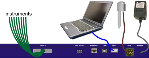
2.1.1 Single CD24-R8 with USB connection
The USB connector on the CD24-R8 can be connected directly to a USB port on a PC or laptop.
The PC or laptop will see the CD24-R8 as a serial device on the USB bus and the operating system will allocate a COM port to it. The CD24-R8 can then be accessed using Scream (File → Setup → Com Ports).
If the PC does not recognise the CD24-R8 as a virtual COM port, you can download drivers from http://www.ftdichip.com/Drivers/VCP.htm
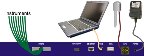
2.1.2 Single CD24-R8 with RS232 connection
The DATA connector on the CD24-R8 can be connected directly to a serial port on a PC or laptop.
The CD24-R8 can be accessed directly using Scream (File → Setup → Com Ports). The default line speed for the DATA connector is 115,200 baud. This rate is suitable for all common usage scenarios and should not normally be changed.
2.1.3 Single CD24-R8 with Ethernet connection
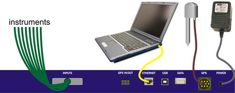
The ETHERNET connector on the CD24-R8 can be connected to your LAN via a network hub or switch. Most modern PCs and laptops also allow a direct connection between the CD24-R8 and the Ethernet port without an intervening hub or switch.
The network interface is implemented using a Lantronix WiPort-NR module. To configure the network settings, please see Chapter 4.
To view the digitiser's output in Scream, open the Network Control window ( +
+ ) and add a new TCP server on port 10,002.
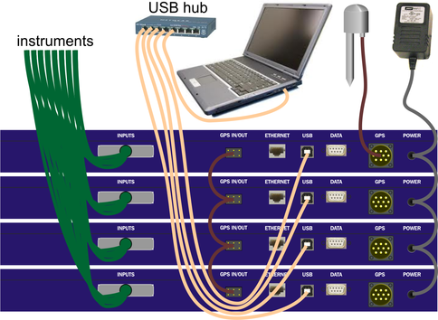
2.1.4 Multiple CD24-R8s without an EAM-R – USB connection
Multiple CD24-R8s can be connected to a single PC or laptop using a USB hub. The individual units will appear as separate COM ports and can be accessed from Scream as described in section 2.1.1.
If the PC does not recognise the CD24-R8 as a virtual COM port, you can download drivers from http://www.ftdichip.com/Drivers/VCP.htm
The GPS receiver should be connected to only one CD24-R8. A GPS “daisy-chain” cable is used to pass timing information to other units in the rack.
The CD24-R8s are supplied with separate power supplies but, if a suitable DC power source is available, a “daisy-chain” power supply cable can be made up to run all the units from a single supply.
2.1.5 Multiple CD24-R8s without an EAM-R – Ethernet connection
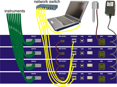
Multiple CD24-R8s can be connected to a single PC or laptop using an Ethernet hub. The individual units will appear as separate network devices and can be accessed from Scream as described in section 2.1.3.
The network interfaces are implemented using Lantronix WiPort-NR modules. To configure the network settings, please see Chapter 4.
The GPS receiver should be connected to only one CD24-R8. A GPS “daisy-chain” cable is used to pass timing information to other units in the rack.
The CD24-R8s are supplied with separate power supplies but, if a suitable DC power source is available, a “daisy-chain” power supply cable can be made up to run all the units from a single supply.
To view the digitisers' outputs in Scream, open the Network Control window (+) and, for each unit, add a new TCP server on port 10,002.
2.1.6 Multiple CD24-R8s with an EAM-R
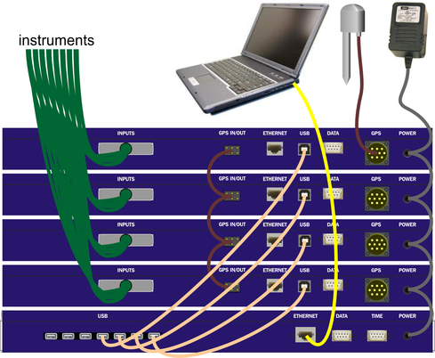
The CMG-EAM-R is a data acquisition device with data-concentration, storage, processing and protocol-conversion facilities. It has been designed for use with up to seven CD24-R8 digitisers. For further information about the CMG-EAM-R, please see document MSH-EAM-0005, available from GSL support (email: support@guralp.com).
Multiple CD24-R8s can be connected to a single CMG-EAM-R using USB cables, as shown.
The GPS receiver should be connected to only one CD24-R8. A GPS “daisy-chain” cable is used to pass timing information to other units in the rack.
The CD24-R8s are supplied with separate power supplies but, if a suitable DC power source is available, a “daisy-chain” power supply cable can be made up to run all the units from a single supply.
2.2 Adjustable Gain
It is possible to adjust the gain of each input channel of the digitiser by connecting a resister between pins 2 and 4 of the relevant input connector (see section 5.1.1 for the pin-outs of these connectors). The gain resistors affect inputs connected to either the front or rear input connectors. High-stability, low-noise components should be used.
The header information in the output packets will not be altered by fitting gain resistors. The gain indicated in the GCF blocks will always be unity. If InfoBlocks or CalVals are used to store calibration information, the values entered should be adjusted accordingly.
Nominal Gain | Resistor value |
Unity | None fitted |
×2 | 18 kΩ |
×4 | 5.8 kΩ |
×8 | 2.5 kΩ |
×16 | 1.2 kΩ |