Chapter 5. Connector pin-outs
5.1 Front panel

5.1.1 Inputs A to H
The front-panel input connectors are 5-way, 3.81mm headers, manufactured by Pheonix Contact, part number MC 1,5/ 5-G-3,81. Suitable mating connectors are provided but can also be obtained from good electronic component retailers. |
|
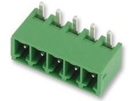
Pin | Function |
1 | Inverting input (-ve) |
2 | Gain resistor |
3 | Signal ground |
4 | Gain resistor |
5 | Non-inverting input (+ve) |
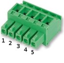
| Wiring details for the compatible plug, Pheonix Contact part number 1827004. |
5.2 Rear panel

5.2.1 Power
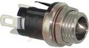
The power connector is a Switchcraft 712A 2.5mm barrel connector wired with the tip +ve and the shield -ve. A 12 - 15V DC regulated supply must be used. There is some variation amongst connectors labelled “ 2.5mm barrel” so it is recommended that mating connectors are purchased from GSL. |
|
5.2.2 GPS
This is a standard 6-pin “mil-spec” socket, conforming to MIL-DTL-26482 (formerly MIL-C-26482). A typical part-number is 02E-10-06S although the initial “02E” varies with manufacturer. Suitable mating connectors have part-numbers like ***-10-06P and are available from Amphenol, ITT Cannon and other manufacturers. |
|
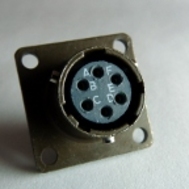
Pin | Function |
A | Isolated ground |
B | RS232 receive from GPS |
C | RS232 transmit to GPS |
D | PPS |
E | not connected |
F | Power +5 V |
| Wiring details for the compatible plug, ***-10-06P, as seen from the cable end (i.e. when assembling). |

5.2.3 DATA
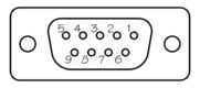
This is a standard DE9F (TIA-574) sub-miniature (D-sub) socket, conforming to DIN 41652 and MIL-DTL-24308. They are very widely available, as are suitable mating connectors. |
|

Pin | Function |
1 | not connected |
2 | RS232 transmitted data (TxD) |
3 | RS232 received data (RxD) |
4 | not connected |
5 | Ground |
6 | not connected |
7 | not connected |
8 | CTS (not required) |
9 | RTS (not required) |
| Wiring details for the compatible plug, DE9M, as seen from the cable end (i.e. when assembling). |
5.2.4 USB
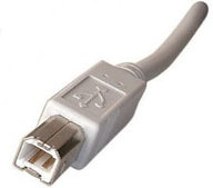
The USB connectors are standard USB type B sockets with conventional wiring. Suitable mating connectors are widely available. |
|
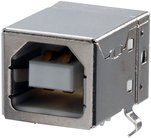
| USB connections are very sensitive to wiring details so it is recommended that ready-made cables are used where possible. |
5.2.5 ETHERNET
The ETHERNET connector is a standard 8P8C modular socket, conforming to TIA/EIA-568-B. It is compatible with standard 10Base-T or 100Base-TX twisted-pair Ethernet connectors. |
|

Pin | Function |
1 | Tx+ |
2 | Tx- |
3 | Rx+ |
4 | Not connected |
5 | Not connected |
6 | Rx- |
7 | Not connected |
8 | Not connected |
5.2.6 GPS In/Out
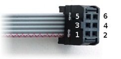
The GPS “daisy-chain” connector is a 0.1 inch pitch header. Compatible sockets are available from good electronic component retailers. |
|

Pin | Function |
1 | NMEA non-inverting input (+ve) |
2 | NMEA inverting input (-ve) |
3 | Ground |
4 | Ground |
5 | PPS non-inverting input (+ve) |
6 | PPS inverting input (-ve) |
| Wiring details for the compatible socket. |
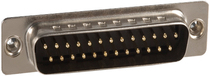
5.2.7 Inputs
The rear-panel input connector is a standard DB25M sub-miniature (D-sub) chasis-plug, conforming to IEC 60807-3, DIN 41652 and MIL-DTL-24308. They are very widely available, as are suitable mating connectors. |
|
Pin | Function |
1 | Channel 1 - Signal ground |
2 | Channel 1 - Non-inverting input (+ve) |
3 | Channel 2 - Inverting input (-ve) |
4 | Channel 2 - Signal ground |
5 | Channel 3 - Non-inverting input (+ve) |
6 | Channel 4 - Inverting input (-ve) |
7 | Channel 3 - Signal ground |
8 | Channel 5 - Non-inverting input (+ve) |
9 | Channel 6 - Inverting input (-ve) |
10 | Channel 6 - Signal ground |
11 | Channel 7 - Non-inverting input (+ve) |
12 | Channel 8 - Inverting input (-ve) |
13 | Channel 8 - Signal ground |
14 | Channel 1 - Inverting input (-ve) |
15 | Channel 4 - Signal ground |
16 | Channel 2 - Non-inverting input (+ve) |
17 | Channel 3 - Inverting input (-ve) |
18 | Channel 5 - Signal ground |
19 | Channel 4 - Non-inverting input (+ve) |
20 | Channel 5 - Inverting input (-ve) |
21 | Channel 7 - Signal ground |
22 | Channel 6 - Non-inverting input (+ve) |
23 | Channel 7 - Inverting input (-ve) |
24 | Channel 1 - Signal ground (duplicate - not required) |
25 | Channel 8 - Non-inverting input (+ve) |