Chapter 4. Typical configurations
Some typical scenarios, with the associated module set-ups, are shown in the following diagrams.
4.1 Single seismic station
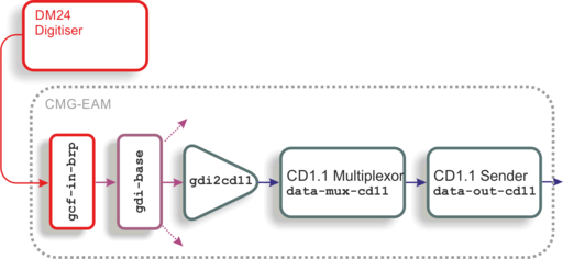
In this scenario, one or more analogue sensor outputs are digitised by a DM24, the output from which is fed over a serial or network link to an EAM or other Platinum system. The data are passed to gdi-base in the normal way and the gdi2cd11 module combines them with state-of-health and other meta-data to form CD1.1 subframes. These are passed to the multiplexor, which assembles them into frames for onward transmission by the CD1.1 sender.
4.2 Central station of an array
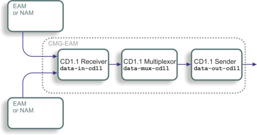
The second diagram illustrates a typical array scenario, where the central EAM accepts full CD1.1 frames from each element and coalesces them, outputting only a single station frame.
4.3 Handling different frame lengths
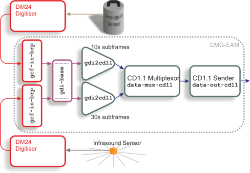
This diagram depicts the use of two gdi2cd11 converter modules to handle subframes with different frame lengths. The multiplexor combines them into a single CD1.1 transmission. Although all the data pass through the gdi-base module, input filtering in the gdi2cd11 instances separates them again so that each can be framed appropriately.
4.4 Different frame lengths from one digitiser
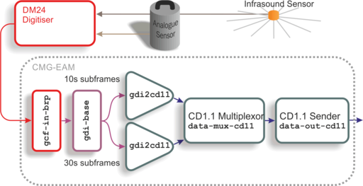
The diagram above shows another way to handle different frame lengths. In this scenario, two sensors of different types are connected to the same DM24 digitiser and their outputs travel together as far as the gdi-base module. Two separate gdi2cd11 modules are then used to implement the different subframe durations, according to the sensor type. The outputs from the converters are then recombined by the multiplexer module and passed to a common sender.