Chapter 6. Using the GDI to CD1.1 converter
This module is used to encode data from non-CD1.1 sources into standards-compliant CD1.1 subframes. It should be used, for example, when data from directly attached digitisers and digital instruments are to be transmitted using CD1.1.
The converter maps incoming channel names to CD1.1 names, which consist of three parts: station (5 characters), channel (3 characters) and location (2 characters), separated by periods. A note in the CD1.1 standard states that the IMS receiving software does not use the location field for anything.
6.1 Creating a new GDI to CD1.1 converter instance
In the web interface, select “Configuration -> Services” from the left-hand menu or from the command line, run
gconfig
and then select “System services”.
Now choose “gdi2cd11 -- CD1.1 converter/subframe generator” to view a list of configured converter instances. You can choose to either configure any existing instance (as described in the following section) or select “Create new service instance” to create a new one.
A form is displayed which allows you to set various parameters for the instance. Each parameter is discussed in the following section. After entering the desired configuration for the instance, click  to save your changes.
This will create (if it is new) and configure the converter instance. If it is not already running, you can start it by using “Control -> Services” on the web menu or by running
/etc/init.local/gdi2cd11.0 start
from the command line.
The zero after the period in the command name determines which converter instance is to be started, so the command to start a second instance would be
/etc/init.local/gdi2cd11.1 start
6.2 Configuration options for the converter
The converter configuration screen has four tabs: "General", "Channel map", "Calibration" and "Monitoring".
6.2.1 The General tab
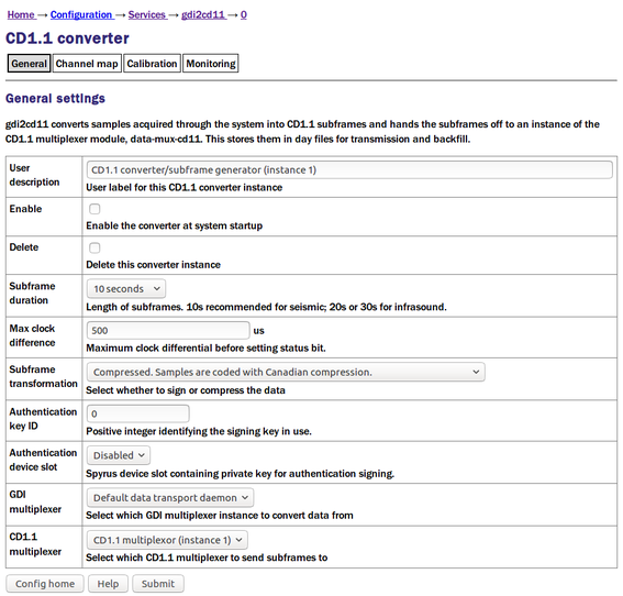
The User description is an alternative, human-readable label for this instance. It is used, for example, in log files. If you are building a complex application with several converters, you should set this to something which describes the function of this particular instance. In most cases, this can be left at the default setting.
The Enable check-box controls whether this instance is to be automatically started each time the system boots or whether it should be left to be started manually.
The Delete check-box, if ticked, will cause this instance to be deleted when the form is submitted.
The Subframe duration field controls the length of subframes. Ten second subframes are recommended for seismic recordings but some applications typically use longer lengths. You can choose between ten and one hundred seconds, inclusively, in ten second intervals.
The Max clock difference field is used to set the “clock differential too large” bit (bit 1 of byte 4, the miscellaneous status byte) in the CD1.1 channel subframe status block . If, for example, a DM24 digitiser loses its GNSS signal, it will use a worst-case drift value to estimate the maximum difference between its internal clock, now free-running, and GNSS time, and report this difference in its state-of-health information. The converter will monitor this value and, should it exceed the value set in this field, it will flag the resulting subframes to indicate that the time-stamp can no longer be trusted. The value is specified in microseconds.
The Subframe transformation drop-down menu controls whether generated subframes are compressed and/or digitally signed. The choices are:
None. Samples are not compressed and the subframe is not signed.
Compressed. Samples are coded with Canadian compression.
Signed. Samples are no compressed. The subframe is signed.
Compressed then signed. The subframes are compressed, then the subframe signed.
The Authentication key ID field sets a flag in the CD1.1 header which some customers use to identify which encryption key pair (from a pre-defined set) has been used. It is generally set to be the serial number of the signing certificate. It should be set to zero if frames are not to be signed.
The Authentication card slot field is used when subframes are signed. The Spyrus card used for signing can store nineteen different key-pairs and this parameter selects which is to be used. If signing is not required, this can be left set to “disabled”.
The converter takes its input from an instance of gdi-base and writes its output to an instance of data-mux-cd11. In most applications, there will be only one instance of each and the remaining two fields, GDI multiplexor and CD1.1 multiplexor can be left at their default values. When building more complex configurations, it may be necessary to have more than one instance of one or both of these modules. These fields let you select, for the converter, which instance of gdi-base to use for input and which instance of data-mux-cd11 to use for output. All configured instances appear on the associated drop-down menus.
6.2.2 Channel map tab
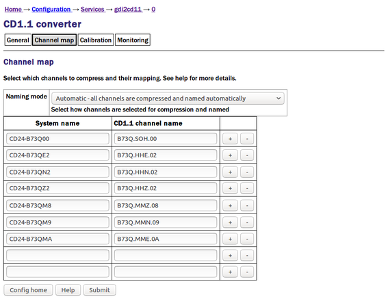
The channel name mapping mode selection drop-down menu allows you to choose between three channel name mapping modes:
In automatic naming mode, the system will automatically generate names for the output channels based on the incoming channel name and any associated meta-data. If the incoming channels have usable names, they will not be changed.
In semi-automatic mode, the mapping in the channel name table will be used. Any channel not named in the table will be mapped with an automatic name (as in automatic mode).
In manual mode, only the channels in the channel name table will be used.
CD1.1 channels are named either STATION.CHANNEL or STATION.CHANNEL.LOCATION where STATION consists of between 1 and 5 characters, CHANNEL of between 1 and 3, and LOCATION (if present) of between 1 and 2. Valid characters are A-Z (upper-case only) and 0-9. The period character in the name serves to separate the components of the name.
If desired, the instrument type and calibration for the channel description fields may be entered into fields in the table. If left empty ("auto" for instrument type), then gdi2cd11 attempts to determine these values automatically.
The columns in the table are:
System name — This is the name as used in gdi-base.
CD1.1 channel name, as STATION.CHANNEL.LOCATION — this is either the system-generated name (in automatic or semi-automatic naming mode) or the user-entered name (in manual or over-ridden semi-automatic naming mode).
Clicking the
 button on any row will open a new row. In the same way, rows can be deleted by clicking the corresponding
  button.
6.2.3 The Calibration tab
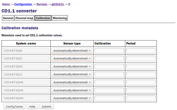
The columns in the table are:
Sensor type — this is a drop-down menu whose options are “Automatically determined”, “Seismic”, “Hydroacoustic”, “Infrasonic”, “Weather” and “Other”. This is used to set the channel descriptor field in the CD1.1 subframe. If this field is set to “Automatically determined”, the type is assumed to be seismic.
Calibration and Period — the values entered here are transmitted in the channel subframe description. Calibration is given in nm/count for a seismic sensor, and period is in seconds. These fields expects floating point numbers, so enter 1.0 rather than just 1. Leaving these fields blank will result in it being automatically populated with default values of 1.0. See chapter 13 for details.
6.2.4 The monitoring tab
The monitoring tab is large and is presented here in three sections. Settings here control various system monitoring options, both binary (on/off) and continuous-valued.
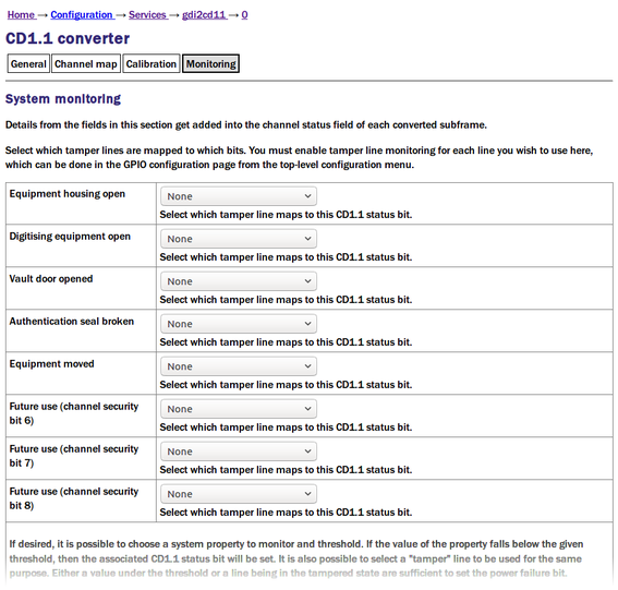
The CD1.1 header has a number of status bits (channel security bits) with predefined meanings related to anti-tamper precautions. Platinum systems have a number of general purpose digital input/output lines which can be configured as inputs from tamper-detection micro-switches and similar devices. The first part of the “System monitoring” table allows the operator to associate each status bit with a specific “tamper line”.
The status bits in the header which can be mapped in this way are:
Equipment housing open;
Digitising equipment open;
Vault door opened;
Authentication seal broken;
Equipment moved;
Future use (channel security bit 6);
Future use (channel security bit 7); and
Future use (channel security bit 8).
For each of these, the “tamper line” that should set this bit can be selected from a drop-down menu. The options on those menus vary considerably depending on the precise hardware configuration of the Platinum system. You must enable tamper-line monitoring for each line you wish to use here: this is done in the GPIO configuration page (directly accessible from the top-level configuration menu).
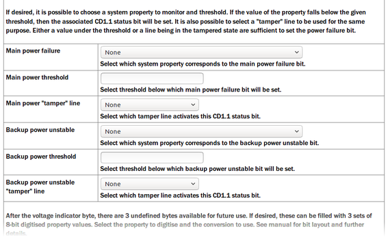
Various continuous values, such as voltages and temperatures, can also be monitored and compared to configurable threshold values. If the threshold is exceeded, a status bit can be set in the CD1.1 header.
The bits that can be controlled in this way are “Main power failure” and “Backup power unstable”. For each of these, a value to be monitored and a threshold value can be configured.
The value to be monitored is chosen from a drop-down menu. The items on this menu vary with the precise hardware configuration of the Platinum system but typically include the choice of voltage, current or power for each monitored power bus. You must enable line monitoring for each value that you wish to use here: this is done in the GPIO configuration page (directly accessible from the top-level configuration menu).
These two status bits can also be set in response to a "tamper" line going high. The required tamper line can be selected from the drop-down menu, if desired.
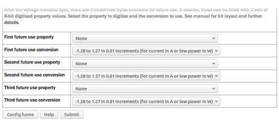
After the voltage indicator byte in the CD1.1 header, there are three reserved bytes available for future use. If desired, these can be populated with three sets of eight-bit digitised property values. The settings shown above allow the operator to select which properties are used to populate these bit-fields and the scaling (units) to be used.
For each of the three bit-fields, the associated property can be selected from a drop-down menu. The items on this menu vary with the precise hardware configuration of the Platinum system but typically include the choice of voltage, current or power for each monitored power bus. The scaling is also set by a drop-down menu, whose choices are:
Current: -1.28 A to 1.27 A where one bit equals 10 mA
Voltage: 5.0 V to 30.5 V where one bit equals 0.1 V
Power or temperature: -64 to 63.5 where one bit equals 0.5 W or 0.5°C (in units of Watts or Celsius, as appropriate).