Chapter 3. First encounters
3.1 Unpacking and packing
The 6TD seismometer is delivered in a single transportation case. The packaging is specifically designed for the 6TD and should be reused whenever you need to transport the sensor. Please note any damage to the packaging when you receive the equipment, and unpack on a safe, clean surface. For each instrument in the packaging, you should have received:
the seismometer;
the breakout box (which provides separate connections for the signal, control and power lines);
a Güralp GPS receiver unit with mounting rod;
a waterproof IEEE.1394 (FireWire) cable;
a 15 metre GPS cable, with six-pin bayonet connectors at both ends;
a power supply cable, with bare wires at one end and a ten-pin bayonet socket at the other;
a serial data cable, with a standard nine-pin D connector at one end and a ten-pin bayonet plug at the other; and
a calibration and installation sheet.
If you have ordered several instruments with a “smart” case, you can test them together using power and data distribution units inside the case: see section 3.3.
Assuming all the parts are present, stand the seismometer in the centre of a bench and identify its external features:
a handle with North indication,
a nineteen-way bayonet plug for data, power and GPS signals;
a six-way bayonet plug for the FireWire interface;
if fitted, a six-way bayonet plug for the Ethernet interface;
if fitted, an antenna connector for the Wi-Fi interface;
a spirit level,
three feet (two adjustable, and one fixed), and
two accurate orientation pins (one brass and one steel).
If the Ethernet interface is fitted, you will also be supplied with a Lantronix configuration cable (part number CAS-PEP-0041).
If the Wi-Fi interface is fitted, you will also be supplied with a small aerial for testing purposes and a Lantronix configuration cable (part number CAS-PEP-0041).
3.1.1 Serial number
The sensor's serial number can be found on the label stuck to the top lid of the sensor. You should quote this serial number if you need assistance from Güralp Systems.
3.2 Test installation
This section gives an overview of how to set up a 6TD and begin recording data. We recommend that you set up a test instrument in your office or laboratory as a “dry run” to gain a basic understanding of the system and to check that it is functioning as expected.
This test installation will use the instrument's default settings. Data will be received using Güralp Systems' Scream! software, available from the website
You will need access to a PC with a nine-pin RS232 port, and a 10 to 28 Volt DC power source. If your PC does not have an RS232 port, you can use an RS232 to USB convert cable. Güralp recommend convertors based on the FTDI chip-set.
Install Scream! on your PC and run it.
Connect the captive cable from the breakout box to the 6TD's nineteen-pin connector.
Connect the six-pin connector on the breakout box to the GPS unit using the brown GPS cable. Position the GPS so that it has a good view of the sky.
If you do not have a view of the sky, you can operate the sensor without a GPS unit but timing information will be inaccurate.
Connect the six-pin data plug on the breakout box to the nine-pin RS232 port on your PC using the serial cable. If your PC does not have a nine-pin COM port, use an RS232/USB converter. Güralp Systems recommend converters based on the FTDI chip-set.
Use the power cable to connect the ten-pin power plug on the breakout box to a fused 10 – 28 Volt DC power source.
Caution: Observe the correct polarity when connecting the power supply. The red lead must be connected to the positive terminal, typically labelled ‘+’, and the black lead must be connected to the negative terminal, typically labelled ‘-’. An incorrect connection risks destroying both the instrument and the power supply.
The instrument is now fully operational, and will already be producing data.
After a few seconds you should see the 6TD's digitiser appear under Network → Local → Com1 in the left-hand panel of Scream!'s main window. (If your PC has multiple serial ports, it may appear under some other COM port name.) Soon after, data streams will begin appearing in the right-hand panel. Streams with higher sample rates will appear sooner than those with lower sample rates.
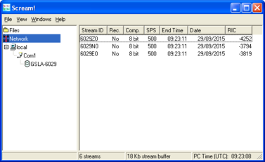
If this does not happen, check all connections, and ensure the power supply is providing the correct voltage and current.
Each data stream has a Stream ID, a six-character string unique to it. Stream IDs normally identify the instrument, component and sample rate of each stream. Thus the stream 1026Z2 refers to a Z-component stream from instrument 1026, at tap 2. For more details on taps and sample rates, see section 4.1.
Data streams ending in 00 are status streams containing state-of-health information sent from the digitiser.
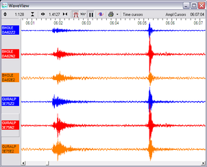
To view data, select a stream and then double-click to open a WaveView window.
You can view several streams at once by holding down
 as you select, and then double-clicking the selection.
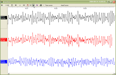
To start recording new data to a file, right-click on a stream or a selection of streams and choose Start recording from the pop-up menu. Recording settings, directories, etc., can be altered by selecting File → Setup… from the main menu and switching to the Recording tab.
To view status information, select the status stream (the stream with an ID ending “00”) and right-click to open a pop-up menu. Select View.
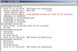
The first few status blocks will consist of the 6TD's start-up messages, including its software revision number and the data streams selected for downloading and triggering.
Later blocks give information on the GPS system (number of satellites visible, the location of the GPS antenna, time synchronization status, etc.) and the baud rates in use for each channel.
3.3 Testing several instruments together
6TD instruments can be ordered in sets of five, with each set delivered in a single, rigid polyurethane transport case.
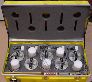
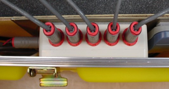
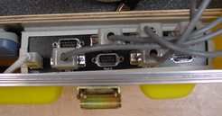
The sensors are packed so that you can huddle-test the sensors and view data in Scream! without needing to unpack them. The case includes a built-in power distribution system, a multi-port serial-to-USB hub and a FireWire hub.
The power and data distribution boxes are located at the front of the case.
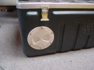
The power supply and combined USB data output cables can be accessed through a waterproof port on the outside of the case.
To test the instruments:
Connect a break-out box to each instrument.
Connect a blue serial cable from each break-out box to the multi-port serial-to-USB hub.
Connect a grey power cable from each break-out box to the power distribution box.
If desired, connect the GPS receivers to the break-out boxes using the brown GPS cables.
Unscrew the port cover, and pull out the ends of the power and USB cables.
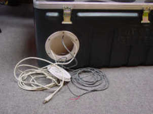
Connect the power cable to your power source, attaching a suitable connector, if necessary.
Connect the USB data cable to your PC.
The internal Digi EdgePort device should be detected automatically. If you need drivers, they can be obtained from Digi International's web site at http://www.digi.com.
Install Scream! on your PC and run it.
After a few seconds you should see the 6TD's digitiser appear under Network → Local → Com1 in the left-hand panel of Scream!'s main window.. (If your PC has multiple serial and USB ports, it may appear under some other Comn port name.) Soon after, data streams will begin appearing in the right-hand panel. Streams with higher sample rates will appear sooner than those with lower sample rates.
If this does not happen, check that the the power supply is providing the correct voltage.
To view data, select the stream or streams of interest and then double-click to open a WaveView window.
You can also add data streams to an open WaveView window by dragging a selection onto it from Scream!'s main window.
In addition to the power and USB data distribution units, the case includes a IEEE.1394 (“FireWire”) hub for you to test high speed data transfer. To do this, connect a FireWire cable from each instrument to the hub.
Once the instruments are connected, you can access them all through the FireWire data cable, which is accessible through the waterproof port in the side of the case.
To download all stored data from the array when it is stored in its transport case, attach a FireWire hard disk to this cable and power up the array using the power cable from the same port.
Be sure to allow enough time for all the data to transfer. The 6TD should be able to transfer data at a sustained rate of around 10 Mb per second, so a full 8 Gb 6TD instrument should take around 12 minutes to transfer all its data.
Note: Some combinations of 6TD and disk hardware cannot support the connection of multiple instruments to a single disk. If you encounter problems like this, connect each instrument individually until the transfers have been accomplished.