Chapter 6. Deployment procedure
.
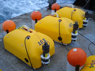
Example of a suitable vessel for OBS deployment and recovery.
6.1 Clock synchronisation
We recommend that GPS synchronisation and clock trimming is carried out on deck as the ship travels to the OBS unit’s deployment location. This ensures that the digitiser clock is synchronised so that the recorded waveforms are accurately timestamped. See Section 5.2 for details on carrying out this procedure. Synchronisation will take at least 30 minutes.
Clock synchronisation being carried out on-deck
6.2 Data recording channels set-up
The CD24 digitiser module in the Güralp Breve samples incoming analogue signals at an initial rate of 256 kHz, using a TI ADS1256 chip set. They are then decimated to 4 kHz using the chip-set's on-board FIR filter. The signal is then passed to a programmable decimation chain, composed of single-stage ÷2, ÷4 and ÷5 FIR filters. Decimation factors of 8, 10, 16, 20 and 40 are achieved by cascading two or three filters in descending order of the decimation factor. Using this arrangement, a large variety of output sample rates can be generated. The CD24 can produce four simultaneous output sample rates.
Note: Consider the available storage volume when choosing output sample rates. A triaxial, 100 sample-per-second recording will normally occupy around 50 MB of storage per day. This value scales linearly with the chosen sample rate.
To select sample rates, right-click on the digitiser's entry in Scream's main window (not the icon for the server or any Comxx icon) and, from the resulting context menu, click Configure…. Scream! will then contact the digitiser and retrieve its current configuration, a process which will take a few seconds. When this is done, the Configuration set-up window will be displayed.
Change to the “Output Control” tab:
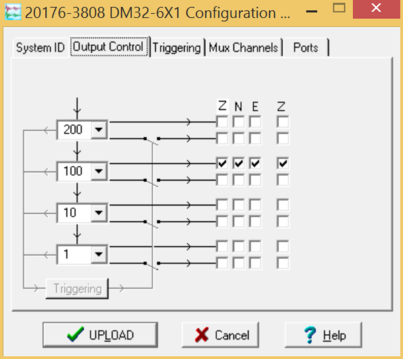
The window displays check-boxes which can be used to enable or disable output on a per-component basis for up to four different sample rates. It also allows control of triggered outputs – the lower set of check-boxes for each sample rate – which are not typically used in this application.
The desired sample rates for each output can be selected using the drop-down menus. Note that the values available at each level depend on the value chosen at the previous (higher) level. This reflects the chain arrangement of the decimation filters.
The example shown above enables three output streams at 100 samples per second and no other outputs. If you wanted, instead, 200 samples per second output, you cannot simply choose 200 from the third drop-down menu because 200 is not a suitable factor of 500. Instead, you could select 200 in the second drop-down menu because this can be achieved by dividing the previous 1,000 samples per second stream by five.
When you have selected the desired sample rates, click to pass the required configuration commands to the digitiser. The digitiser will reboot automatically so that the changes can take effect. This will interrupt data flow for no more than five minutes.
Right-click on the digitiser's entry in Scream's main window (not the icon for the server or any Comxx icon) and, from the resulting context menu, click Control…. Scream! will then contact the digitiser and retrieve some current configuration settings, a process which will take a few seconds. When this is done, the Control set-up window will be displayed.
Change to the “Data Flow” tab:
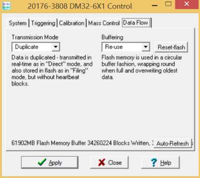
Ensure that the transmission mode is set to “DUPLICATE”.
Caution: Some Transmission Modes, such as “DIRECT” do not store data so it is essential to select “DUPLICATE” mode at this point. For more information, please see Chapter 8 of the Scream manual, MAN-SWA-0001.
In the “Buffering” drop-down menu, you can choose between “Write-once” and “Recycle” modes. This setting affects what happens if your deployment lasts longer or generates more data than expected.
In “Write-once” mode, no more data will be written to Flash once it is full. This setting prioritises data from the beginning of the deployment.
In recycle mode, once the Flash memory is full, new data will over-write the earliest data in memory. This setting prioritises data from the end of the deployment.
Clicking the button on this screen will mark the flash memory as unused, which can simplify data selection at the end of a deployment.
Once the desired settings have been made, click to write the settings to the configuration memory.
At this point, it is a good opportunity to perform a visual check on the signals being recorded on the seismometer and hydrophone channels.
From the control menu, please check that the auto-levelling of Gimbals is set to 50%.
6.3 Cable connections
Just prior to deployment, check that the octopus cable is connected to both the sensor/digitiser canister and the battery canister. Ensure that the Aquamate connector dummy cap is fully attached to the octopus cable. Check that all underwater connectors have tight locking sleeves. Check that the buoy release system is properly set (Section 5.4).
6.4 Lowering and releasing
The process of lowering and releasing should be carried out by a minimum of four personnel.
Prepare the ship’s winch. The winch’s lifting line must have a maximum length that is greater than the deployment depth.
Follow completion of the above steps, the OBS can be attached to the lifting line to get it ready to the deployment.
An Ixsea OCEANO 2500 Light acoustic release (total weight: 26 km) is optionally provided by Guralp and it will be attached at the end of the winch line to release the OBS units on the seabed. The acoustic release has been shipped with a 1 m strop and the OBS should be attached to the acoustic release as shown in the following picture.
To stop the OBS swinging during deployment, attach two tag lines to the OBS handle.
Using the ship’s A-Frame, lift the OBS unit slightly above the deck and move out the A-Frame so that the OBS is over the water and safely dear of the ship.
Lower the OBS in the water about 1 m below the sea surface to stop the swinging. Start lowering the OBS to the seabed. The ship’s Captain has to try to hold the boat position during deployment operations.
When the OBS is on the seabed, send the RELEASE command to the OCEANO 2500 using the Acoustic Command Unit to release the OBS on the seabed and retrieve the acoustic release.
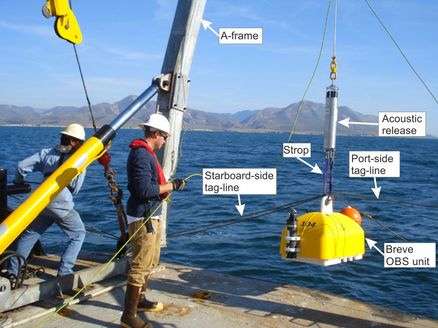
Lowering of an OBS unit into the sea using the vessel’s A-Frame