Chapter 6. Data Handling
6.1 Introduction
The data handling system of the acquisition module is very flexible, due to its modular software architecture. In the simplest configuration, all data flowing through the acquisition module is routed through a single multiplexor module called gdi-base. This communicates directly with all input modules, which handle the various incoming data streams, and all output modules, which convert the data into the required formats. All incoming data are stored and accessed internally in an intermediate format, regardless of the format in which it was originally received.
Note: The sole exception to this is incoming CD1.1 data which, for reasons related to frame signing (an authentication technology), do not pass through gdi-base. CD1.1 data-handling and the associated system configuration are covered in a separate manual, MAN-EAM-1100, which is available for download from www.guralp.com.
The diagram below shows the basic internal organisation of an acquisition system, ignoring the CD1.1 subsystem:
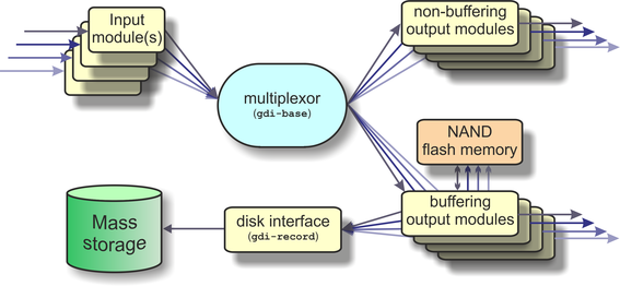
The multiplexor makes incoming data available to the output modules. These come in two flavours: simple modules (such as those for WIN, GSMS and QSCD) simply convert the data streams and output them in the required format; other modules maintain a ring-buffer which is used to, for example, satisfy BRP back-fill requests. The ring-buffers use the NAND flash memory. These output modules also send data to gdi-record, which handles all mass storage device writing requests, regardless of format.
The gdi-base and gdi-record programs are designed to be stateless, so that the data on the mass storage device are always consistent. This means the system is tolerant of power interruptions and of the mass storage device being removed without notice.
Any number of input modules can be configured to acquire data in any supported format from any source, simultaneously. These modules convert their data and pass it to the multiplexor. Data can be acquired in any of the following formats, from multiple sources:
BRP via serial lines
Scream, via Ethernet or ppp
GDI-link, via Ethernet or ppp
CD1.1
The architecture has been designed to support the addition of extra formats simply by adding input modules. Please contact Güralp Systems if you have requirements which are currently unsupported.
Any number of output modules can be configured to send data in any supported format to any destination. The following data formats are supported:
GCF output via serial port or TCP stream
GCF output via Scream (TCP or UDP)
SEEDlink
CD1.1;
GDI (Güralp Data Interconnect)
GDI-link
WIN format output
QSCD - Quick Seismic Characteristic Data (designed by KIGAM) output
GSMS (Güralp Seismic Monitoring System) output
In the default, factory configuration, the acquisition module is configured to receive serial GCF input on all of its serial ports except Data Out. There is a single chain of data through the multiplexor to a Scream server. Data are also recorded to the configured mass storage device in GCF format. This is shown in the following diagram:
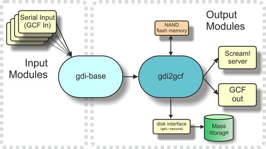
The gdi2gcf module, know as the GCF compressor, is responsible for re-blocking GDI samples into GCF blocks. It provides data to all GCF output modules as well as to the gdi-record module, which writes GCF files to the mass storage device. It has a number of configuration options, which are described in section 11.2.
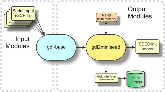
A similar arrangement applies to miniSEED data: the gdi2miniseed module provides data to the SEEDlink server and to gdi-record.
6.2 Configuring gdi-base
The gdi-base module requires no configuration in most applications. For very complex situations, however, it may be necessary to create additional instances. The information in this section is provided the interests of completeness.
To configure a gdi-base instance on the acquisition module from the web interface, select:
Configuration → Service → Expert → Advanced
or
Configuration → All options → System services → Expert → Advanced
To configure an instance from the command line, start gconfig and select “System services” from the top level menu.
Now select “gdi-base -- Data transport and channel manager”.
The screen shows a list of all gdi-base instances that have been configured. Select the appropriate link to edit an existing instance or to create a new one.
6.2.1 Configurable parameters
The configurable parameters for gdi-base are contained in a single form:
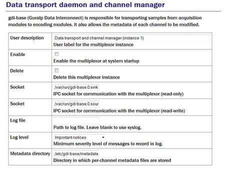
User description: Sets the name of the instance; this should be set to a meaningful name for the function it will be performing.
Socket: Allows specification of the inter-process communication socket used by this instance. This should not normally be changed.
Log file: It may sometimes be desirable, for debugging purposes, to separate log messages for this transmitter from the standard system log. The text field can be populated with a path name which will then be used for dedicated logging. If left blank, logging occurs (via the standard Linux syslog facility) to /var/log/messages.
Log level: The drop-down menu controls the level of detail present in log messages, whether to syslog or to a dedicated log file. Not all of the standard syslog logging levels are available. The menu offers a choice (in order of decreasing detail) of:
Debugging information
Informational messages
Important notices
Warnings
Metadata directory: Allows specification of the directory where this instance stores intermediate information. This should not normally be changed
6.3 Using compressors
The two compressors mentioned at the beginning of section 6 convert from GDI to GCF and from GDI to miniSEED format. They provide channel filtering, channel name mapping and data buffering for the gdi-record module, which writes GCF and miniSEED files to the mass storage device.
One instance each of gdi2gcf and gdi2miniseed are present in the default configuration. Additional instances may be created as required. This will be necessary if you have different channel filtering requirements for, say, recording and transmitting or if you need different transmitters to send different sets of channels to different destinations. The configuration page for every transmitter has, in the “Expert mode” options, a drop-down menu which allows the operator to select which compressor instance to use for its input. The gdi-record configuration page has a similar facility.
Instances of either compressor are “dependant services”, meaning that they do not need to be (and should not be) configured to start automatically when the system boots. They will be started whenever a client service, such as a connected transmitter (or gdi-record), starts.
Configuration of the GCF compressor, gdi2gcf, is described in section 12.1.1.
Configuration of the miniSEED compressor, gdi2miniseed, is described in section 12.2.1.