Chapter 8. Digitiser Configuration
8.1 Configuring digitisers using the web interface
The configuration interface can be used to configure the digitiser module in a DAS or any serially attached Güralp digitiser, such as CMG-DM24 or CMG-CD24. The internal digitiser module in a CMG-DAS is, effectively, serially connected so both internal and external digitisers are handled identically.
To configure a digitiser using the web interface select:
Configuration → Instruments → Port A instrument....
The list alters dynamically to reflect the system's embedded and attached devices. For every digitiser detected, an entry appears which allows you to configure the digitiser.
Note: To control (as opposed to configure) the digitiser and its attached instrument (sensor locking, mass centring, etc.) see section 14.3.2.
The information shown on this screen is retrieved from the digitiser using a sequence of background commands over a serial communications line and may, therefore, take a few seconds to display. A progress indicator is displayed during this process. It is possible to display this sequence of commands (together with the responses received from the digitiser) and this may be useful both for learning the command-line interface of the digitiser and for debugging any unexpected behaviour. To do this, select “Show full digitiser dialogue in future form submissions” from the miscellaneous section near the bottom of the configuration screen.
Note: This is a web form and, therefore, no changes will be made to the actual configuration of the digitiser until the form is submitted – i.e. until the operator scrolls to the bottom of the page and clicks  .
.
8.1.1 Configurable parameters
The digitiser configuration screen is too large to be reproduced in one illustration in this manual. It is, therefore, shown here in sections.
8.1.1.1 Identity
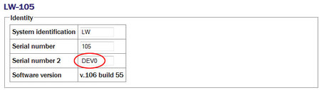
The first section displays the digitiser's identification string and serial number, which can be edited. It also displays the digitiser's software version:
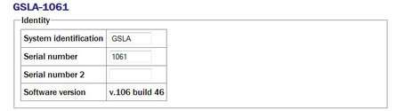
System identification / Serial number: Make any desired changes and then click on the button at the bottom of the screen. If the digitiser is running in dual serial mode, both serial numbers are displayed on this screen in separate rows.
8.1.1.2 Connected devices
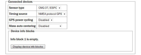
Sensor type: Has no effect on the acquisition module's operation and acts as a memo field.
Timing source: Set to “NMEA protocol GPS” (which should be used for all GPS devices) or “None”, for situations where there is no timing source.
GPS power-cycling: GPS units can be turned off to save power in battery-powered environments. In order to keep the internal clock synchronised, the GPS unit is regularly turned on for long enough to obtain an accurate time and then turned off. The GPS power-cycling drop-down allows you to select the intervals at which this happens (1, 2, 3, 4, 6, 8, 21 or 24 hours) or whether to leave the GPS constantly powered up.
Mass auto-centring: The drop-down menu can be used to configure (or disable) a digitiser function which automatically initiates a round of centring when the mass position (averaged over several minutes) drifts further than the specified distance from zero. The excursion required to trigger centring is expressed as a percentage of full scale.
8.1.1.3 InfoBlocks
InfoBlocks (information blocks) are one-kilobyte areas of storage within the digitiser which can hold arbitrary data. In some applications, such as when a digitiser is generating strong motion packets, they should hold structured information about the attached sensors. Newer digital sensors have their calibration information pre-loaded into the InfoBlock. The format of the data is given at http://www.guralp.com/information-blocks-from-guralp-digitizers/ but you can add any additional information that you find useful, such as asset tracking information, provided you don't exceed the one-kilobyte limit.
Digitisers automatically transmit the InfoBlock, if it is set, at every reboot. The block is transmitted with a special stream ID ending “IB”. Retransmission of the InfoBlock can be requested at any time by issuing the digitiser command SENDINFO. If a copy of Scream receives an InfoBlock, it will scan it for calibration values and incorporate any that it finds into its calvals.txt file. This information is used for displaying streams in ground units (rather than counts) amongst other things.
There are one or two info blocks per digitiser and the display will recognise this fact. The  button(s) show the contents of the info block(s) and allows you to upload new data to them, should you wish. When the button is clicked, the following is displayed:
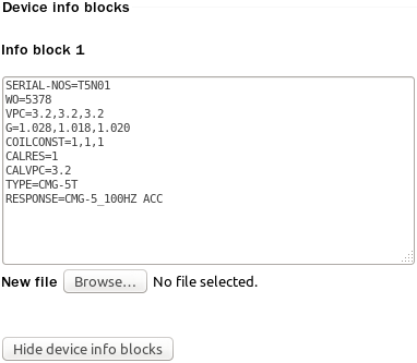
A file containing the desired InfoBlock text can be uploaded by clicking the  button: the web-browser's normal upload facility is used.
Clicking the  button returns the display to the previous state.
8.1.1.4 Causal filtering (low latency) and Strong motion mode
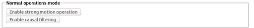
The next section of the screen controls the filtering mode of the digitiser and optionally enables strong motion calculations. Causal filtering mode (previously called “low latency” mode) is intended for use with strong motion calculations. In this mode, the last stage of the digital filtering is changed from finite impulse response (FIR, acausal) to infinite impulse response (IIR, causal) and packets are output each second at twenty samples per second in order to achieve very near real time data.
These modes cannot be selected unless the first decimator output is set to two hundred samples per second. The  button is enabled only when this condition is satisfied.
CMG-DM24 digitisers can operate in “normal” mode or “strong motion” mode. In strong motion mode, additional “strong motion packets” are generated; these carry derived and resultant data.
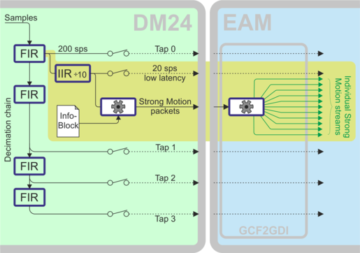
The DM24 uses the calibration information from the InfoBlock (see section 8.1.1.3) to compute values such as minima, maxima, averages and two- and three-dimensional resultants in ground units, all of which are contained in the strong motion packets. The InfoBlock must be correctly populated for this to work. The acquisition system demultiplexes the strong motion packets and generates individual GCF streams for each type of data. Because GCF streams can only carry integer values, the floating point values from the strong motion packets are each multiplied by 32767 before being packed as GCF data.
Strong motion mode requires that the highest tap (the one with the fastest sample rate) is set to 200 samples per second. The 200 sps data are passed through a fast-response, divide-by-ten IIR filter in order to produce the low-latency 20 sps data which are used for the calculations. This 20 sps low-latency stream can be enabled for direct output: it's stream ID will have the suffix 'E'.
Strong motion mode can be configured using buttons on the web page. If the highest tap is configured for 200 samples per second operation, the following is displayed:
If the highest tap is not set to 200 samples per second, an additional button is displayed:
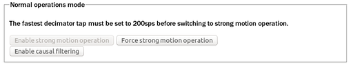
The  first reconfigures the taps so that the highest tap is set to 200 samples per second and then enables strong motion mode. If the highest tap is already set to 200 samples per second, the
  button is active and, when clicked, enables strong motion mode.
When in strong motion mode, this section of the screen displays as:
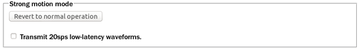
The “Transmit 20sps low-latency waveforms” check-box enables or disables the 20 samples per second stream, which is used internally to provide the data for the strong-motion calculations but can also be transmitted, recorded, and used like any other output stream.
Clicking the  button cancels strong motion mode and returns the CMG-DM24 to normal operation.
The thirty additional streams produced when in strong motion mode are shown in the following table, where S represents the System ID and C identifies the component ('Z' for vertical, 'N' for North/South or 'E' for East/West).
Stream ID | Data content |
SCO | Windowed minimum for component |
S2O | Windowed minimum for horizontal resultant |
S3O | Windowed minimum for 3-dimensional resultant |
SCP | Windowed PGA for component |
S2P | Windowed PGA for horizontal resultant |
S3P | Windowed PGA for 3-dimensional resultant |
SCQ | Windowed maximum for component |
S2Q | Windowed maximum for horizontal resultant |
S3Q | Windowed maximum for 3-dimensional resultant |
SCR | Windowed RMS for component |
S2R | Windowed RMS for horizontal resultant |
S3R | Windowed RMS for 3-dimensional resultant |
SCS | Windowed SI for component |
S2S | Windowed SI for horizontal resultant |
S3S | Windowed SI for 3-dimensional resultant |
SCT | Windowed average for component |
S2T | Windowed average for horizontal resultant |
S3T | Windowed average for 3-dimensional resultant |
8.1.1.5 Causal filtering
The normal decimation chain on a CMG-DM24 uses acausal finite impulse response (FIR) filters. Acausal FIR filters have significantly higher latency than causal FIR filters. The last filter in a decimation chain has the biggest effect on the overall latency of the chain. The CMG-DM24 offers a single causal FIR filter which can be connected at any point in the decimation chain to provide a lower-latency output.
To enable the causal FIR filter, ensure that the CMG-DM24 is in normal operation mode (not strong motion mode) and then click . Scroll to the bottom of the page and click .
Once the digitiser has rebooted, a new section appears on the screen, as shown below:
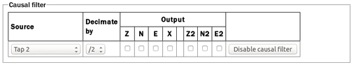
The “Source” drop-down menu allows you to select the tap that will be used as the input to the causal filter (which need not, therefore, be the final filter in the decimation chain). The “Decimate by” drop-down menu allows you to select the divisor implemented by the filter. The “Output” check-boxes allow you to select which components to output via the causal filter.
The causal filter may be disabled by clicking the  button, then scrolling to the bottom of the page and clicking .
8.1.1.6 Compression mode

Compression mode: Controls how samples are packed, affecting both data latency and line utilisation. GCF packets contain a 32-bit starting value and then a series of differences between consecutive samples. When the input signal is relatively quiet, these differences can often be expressed as 8-bit quantities. When the input signal includes large transients, the differences are transmitted as 32-bit quantities. For intermediate level signals, 16-bit values can be used. This is known as compression as it can “compress” four samples into the space otherwise occupied by a single value. The digitiser can be configured to limit the amount of compression used, decreasing latency.
The difference values are stored in records, which are four bytes long and, so, may contain four 8-bit differences, two 16-bit differences or one 32-bit difference. A GCF packet can contain up to 250 records so the maximum number of samples in a packet is between 250 (when 32-bit differences are used) and 1000 (for eight-bit differences).
Packets must start on whole-second boundaries, so they are not always filled. In addition, it is possible to configure the digitiser to further restrict the number of records in a packet in order to decrease latency.
The drop-down menu controls both of these settings and normally offers the following choices:
Recommended for 200sps or less (8 bit 20 records, maximum 80 samples): - Represents the best compromise for throughput: allowing 8-bit compression potentially increases the number of samples per packet and limiting packets to twenty records guarantees reasonably low latency.
Maximum, recommended for 250sps or more (8 bit 250 records, maximum 1000 samples): - Optimises line utilisation, allowing maximum compression and minimising the number of packet headers transmitted.
Minimum for lowest latency (32 bit 5 samples): - Disables compression, forcing samples to be transmitted as 32-bit differences. Latency is reduced by limiting the number of records to one per packet.
If the system is connected to a digitiser that is using a different combination of compression control and sample limits, it will appear as an extra item in the drop-down menu, labelled Custom. For example: Custom (16-bit 40 samples max) would appear if these settings had been manually configured from the digitiser's command line.
8.1.1.7 Decimator outputs
The decimator outputs control which digitiser taps have been configured to output data, both in continuous and triggered states.
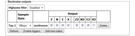
On four-channel digitisers, only the columns Z, N, E and X are displayed. On seven-channel digitisers, Z, N, E and X represent the outputs from SENSOR A and Z2, N2, E2 and X2 represent the outputs from SENSOR B.
Note: Do not confuse SENSOR A and SENSOR B, which are analogue inputs to the digitiser, with Port A and Port B, which are digital inputs to the EAM.
An optional Highpass filter can be applied to eliminate the effect of any DC offset in the sensor's output. The available corner frequencies, 100, 300 and 1000 seconds, can be selected from the drop-down menu.
The table below the filter configuration shows the currently configured continuous and triggered outputs with components in columns and taps in rows. The number of output columns increases when using seven-channel digitisers.
Extra taps can be added with the  button. The rates available at each tap are dependant on the rate selected at the previous tap: the base sampling rate is 2000 samples per second and each tap can be configured to divide this by either 2, 4 or 5. The available rates are shown in the table below, along with a way to configure each, although there are sometimes very many different ways to configure any given rate.
Desired | Intermediate |
4 | 400, 100, 20 |
5 | 400, 100, 20 |
8 | 400, 200, 40 |
10 | 400, 100, 50 |
16 | 400, 80 |
20 | 400, 100 |
25 | 400, 100 |
40 | 400, 200 |
50 | 400, 250 |
80 | 400 |
100 | 400 |
125 | 500 |
200 | 400 |
250 | 500 |
400 | tap 1 |
500 | tap 1 |
1000 | tap 1 |
The triggering settings are normally hidden but can be revealed by clicking the  or
or  button. The following extra dialogues are displayed:
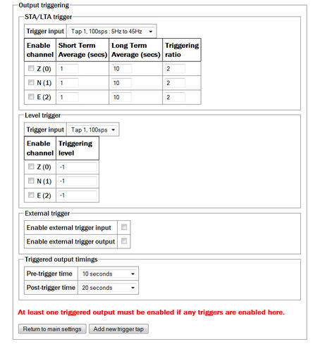
STA/LTA triggers: Activate when the ratio of the short-term average to the long-term average (of the input signal) exceeds a configured value.
Trigger input: The drop-down menu allows the selection of the input signal to be used for these calculations, along with one of three filter settings. The available filters have lower corner frequencies based on fixed fractions of the sample frequency: specifically, 5%, 15% and 25% of the sample rate. The upper corner is 0.9 times the Nyquist frequency (45% of the sample rate).
For example, if a tap configured for 25 samples per second, the three filters offered will have pass-bands of:
1.25 Hz to 11.25 Hz (5% of 25 Hz is 1.25 Hz and, as the Nyquist frequency for 25 samples per second is 12.5 Hz, 0.9 × 12.5 = 11.25);
2.5 Hz to 11.25 Hz (15% to 45% of the sample rate); and
6.125 Hz to 11.25 Hz (25% to 45% of the sample rate).
Note that the filtering specified here is applied to the specified tap output before being used for trigger input but does not affect the tap output if it is also used to generate continuous streams.
The periods over which the short term and long term averages are computed, along with the triggering ratio itself, can be altered by changing values in the table. The check-boxes next to each component are used to enable or disable the use of that component's output in the STA/LTA triggering algorithm.
The tap to be used as input should be selected from the Trigger input drop-down menu. All configured taps are available, regardless of whether they have been selected for continuous output or not.
The check-boxes labelled with component designators are used to include or exclude the associated component from the triggering algorithm. If one is ticked, a trigger will be activated if that component's instantaneous output exceeds the value entered into the Triggering level field in the same row.
Full coverage of external triggering is beyond the scope of this manual and the interested reader is referred to the relevant digitiser manual.
The pre-trigger time and post-trigger time drop-down menus control the amount of data transmitted around each trigger period. The options offered range from 5 seconds to 4 minutes. The “0 seconds” setting disables the feature.
The  button inserts and extra row in the decimator output table and returns the display to the main digitiser configuration settings screen.
8.1.1.8 Multiplexor channels
The next section of the main display shows and controls the transmission of data from the auxiliary and state-of-health channels of the digitiser:
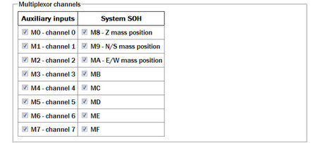
Inputs M3 through M7 and MB through MF are typically derived by digitising (at 16-bit resolution) the analogue inputs on the “Auxiliary” connector of the digitiser although, in some configurations, they may be connected to internal sensors. For example, ME is often used for an internal temperature sensor and M8, M9 and MA provide mass position data from the first sensor. Output from each displayed channel can be enabled by ticking the associated check-box or disabled by clearing it.
8.1.1.9 Transmission mode
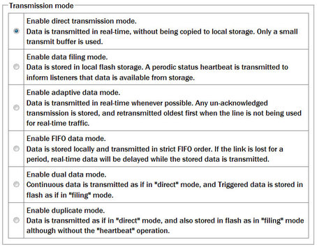
The Transmission mode selections are exactly as defined on the form.
Note that Direct is the default and preferred method of transmission
8.1.1.10 Storage Mode
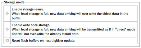
In the storage mode section, selecting the Reset flash buffers on next digitiser update check-box will cause all data in the flash storage to be erased and the read pointers to be reset.
Note: Use this facility with caution. Data will be erased so, if they are important, ensure that they have been flushed to storage and are readable before clearing the buffer.
8.1.1.11 Transmission Parameters

Heartbeat interval: When the digitiser is in the “filing” or “dual” transmission modes regular heart-beat messages are sent. This allows software such as Scream to be aware of the devices even though they are not sending sampled waveform data. The frequency of these messages can be set to an integer number of seconds.
Acknowledgement delay: When the digitiser is in the “adaptive” or “FIFO” transmission modes, special action is taken if data cannot be transmitted. The acknowledgement delay field controls how long the digitiser waits for an acknowledgement packet before assuming that the link has failed. This should be set to an integer number of milliseconds.
8.1.1.12 Ports
The Ports section of the web page allows control of the baud rates of the digitiser's serial ports:
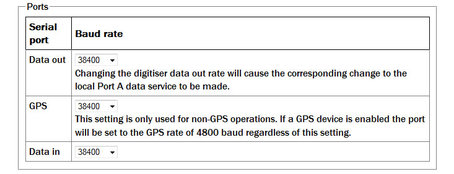
For a stand-alone digitiser or digital instrument, the “GPS” and “Data in” ports are exposed on external connectors. The “Data out” port is assumed to be connected to the acquisition module and the rate set here must match that set for the appropriate serial port (see section 10.1 for details of reconfiguring serial ports).
Note: For CMG-DAS systems, the digitiser's “Data out” port is connected internally to the CMG-EAM module's “Port A” and both ports must use the same Baud rate. The digitiser's “Data in” port is used to provide a console for the digitiser (without interrupting seismic data transmission) and is connected internally to the CMG-EAM module's “Port B”. Again, both ports must use the same Baud rate. The digitiser's “GPS” port is connected to the CMG-EAM module's “Port C”. This connection can be used in two ways: the acquisition module module can share with the digitiser the data from the physical GPS receiver and use it as an NTP clock source (see section 7.4); or, alternatively, the acquisition module module can be synchronised to another time source (such as Internet NTP) and provide NMEA signals to the digitiser module. In either case, the digitiser module's “GPS” port and the acquisition module module's “Port C” must use the same Baud rate.
If a stand-alone digitiser or digital instrument is fitted with a Lantronix Ethernet or WiFi option, it uses the “Data out” port settings for its internal communications with the digitiser. Changing the associated Baud rate requires making a network connection to the Lantronix unit's web interface and selecting the matching baud rate from its control page.
8.1.1.13 Miscellaneous features and Submission
The final section of the digitiser control web page is entitled “Miscellaneous features”. This section displays a warning in red if a discrepancy is detected between the EAM's time and the digitiser's own clock. If the two clocks have reasonable synchronisation, this message is suppressed. A typical warning looks like this:
Digitiser clock is displaced by more than 5 minutes from the system clock. (Plus 7 minutes).
This section of the page is shown here without the warning:
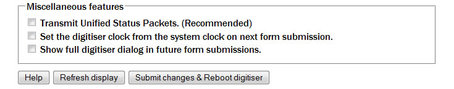
The first check-box enables the transmission of Unified Status Packets. Unified Status Packets are a machine-readable representation of the data carried in the normal, human-readable status streams and allow programs such as Scream to access complete and consistent state-of-health information regardless of any status stream customisations.
The second check-box allows the one-time re-synchronisation of the digitiser to the EAM's system clock. The third toggles display of the underlying dialogue with the digitiser, as described at the beginning of this section.
Note that, as with all web interfaces, options selected on this screen will not take effect until the page is submitted.
An extra button at the bottom of this page,  , causes the system to re-query the digitiser for its current configuration settings, allowing the refreshing of the web page display with up-to-date information.
Note: Submitting this page, whether or not changes have been made, will reboot the digitiser.
8.2 Configuring digitisers from the command line.
Platinum provides two command-line tools to allow configuration and control of digitisers and the instruments connected to them, adc-command (see section 8.2.1) and data-terminal (see section 8.2.2). The adc-command feature allows specific instrument control commands to be sent to digitisers while data-terminal exposes the digitiser's console, allowing arbitrary commands to be sent.
In addition, the dm24-upgrade tool (see section 8.2.3) allows the firmware of attached digitisers to be upgraded from the command line of the acquisition device.
8.2.1 adc-command
The adc-command tool allows a number of instrument mass control commands to be issued to attached digitisers. For further details, see section 14.3.2.2.
8.2.2 data-terminal
Platinum provides a tool, data-terminal, which allows direct access to the command-line of any serially attached digitiser. This gives the greatest level of control but also involves the most complexity.
Interactions with the digitiser's command-line are beyond the scope of this document: please consult the relevant digitiser manual for information on this topic. This section discusses use of the data-terminal tool only.
To invoke the tool, enter the command
data-terminal
You will be presented with a menu listing all digitisers to which a connection can be made:
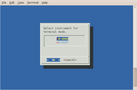
Select the required digitiser from the menu. The data-terminal program will suspend any service running on the associated port and start a minicom session with the correct communications parameters already set.
The use of minicom is described in section 16.3. When you have finished configuring the digitiser, key  +
+ then
then  to exit. Any previously running service will be restarted.
8.2.3 dm24-upgrade
The dm24-upgrade tool provides a command-line facility to upgrade the firmware on attached CMG-DM24 and CMG-CD24 digitisers. Each release of Platinum firmware contains the latest firmware images for both digitiser types. You may wish to upgrade your Platinum firmware (see section 5 for details) before using this command.
To perform a simple upgrade, enter the command
dm24-upgrade id
replacing id with the port identifier (typically PortA or PortB) or the digitiser's ID (as reported by, for example, the data-terminal command described in the previous section).
More complex operations are possible; these are invoked by placing command-line arguments between the command and the port identifier, as in:
dm24-upgrade arguments id
The available arguments are described in the following paragraphs.
--trashfram ― Perform a hard factory reset, all parameters will be lost.
--ids sys ser ― Specify new system ID and serial number to set following a hard factory reset. This option will attempt to preserve the previous values if new values are not specified)
--samp # # # # ― Change the sample speeds for each of the four decimation taps. This option requires four numeric values as supplied for the SAMPLES/SEC command described in the DM24 manual.
--cont # # # # ― Change which streams are produced as continuous output from each of the decimation taps. This option requires four numeric values as supplied for the CONTINUOUS command described in the DM24 manual.
--trig # # # # ― Change which streams are produced as triggered output from each of the decimation taps. This option requires four numeric values as supplied for the TRIGGERED command described in the DM24 manual.
--gps-baud # ― Set the line speed for the GPS port. This option requires a single numeric value: the new line speed to use.
--in-baud # ― Set the line speed for the DATA IN port. This option requires a single numeric value: the new line speed to use.
--upgrade ― Upgrade firmware files only (this is the default).
--downgrade ― Allow firmware files to be downgraded as well as upgraded.
--force ― Firmware files are to be loaded even if they appear identical, or the installed version number cannot be decoded.
--boot file ― Specify a source file for DM24mk3 bootstrap. This option requires a single value, file, which is the path to the firmware image file to be loaded.
--firm file ― Specify a source file for DM24mk3 or CD24 firmware. This option requires a single value, file, which is the path to the firmware image file to be loaded.
--dsp file ― Specify a source file for DM24mk3 DSP code. This option requires a single value, file, which is the path to the firmware image file to be loaded.
--auto-baud ― Scan for digitiser baud rate and adjust configuration. If possible.
--verbose ― Show most of the digitiser dialog.
--debug ― Output some additional debug information from the underlying expect script.
8.3 Configuration for a second instrument
When the acquisition module detects that an attached (or built-in) digitiser supports a second instrument (SENSOR B), additional items appear on the web interface menu for the digitiser.
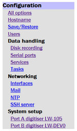
To use a second instrument, click the link for the associated digitiser in the “System Setup” sub-menu of the “Configuration” menu. The resulting screen will display a text-field, Serial number 2. Populate this field with the serial number of the second sensor (or any desired value) and submit the page, rebooting the digitiser.
Wait a short while and then use the refresh facility in your web browser to reload the main menu. An extra device will appear in the “Control” section of the main menu and an extra link for the digitiser will appear in the “System Setup” sub-menu of the “Configuration” menu:
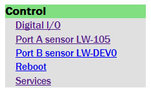
Although there are two links on the 'Control' section, only the first sensor can be controlled.
Both links for the digitiser take you to the same page and either may be used (This allows recovery from the situation where two physical digitisers with the same serial numbers have been connected).
If either of these links are selected, the resulting page differs slightly from that described in Section 8.1.
The “Device info blocks” section now displays the status of two Info blocks - one for each connected sensor. The “Display device info blocks” button takes you to a screen from where you can edit both.

Extra columns appear in the “Decimator outputs” configuration section:

Streams from the second sensor are enabled or disabled by ticking or clearing the check-boxes in the columns labelled Z2, N2 and E2. An X2 stream will appear in this table when a seven- or eight-channel digitiser is detected, but it is not available on a seven-channel digitiser.
Notes:
The second sensor is assumed to be an accelerometer. No provision is made for mass control (locking, unlocking and centring) of SENSOR 2.
The Sensor type drop-down menu in the digitiser configuration page refers to the first sensor only. SENSOR 2 is assumed to be an accelerometer.
InfoBlock 1 refers to SENSOR 1 and InfoBlock 2 refers to SENSOR 2. Values entered in these InfoBlocks are passed to Scream, which will apply them to the correct data streams.
Multiplexor outputs M8 (Z mass position), M9 (N/S mass position) and MA (E/W mass position) refer to SENSOR 1 only.
When configuring triggering, input streams are available from both sensors (at the selected tap). When a trigger condition is detected, configured outputs from both sensors are enabled, regardless of which sensor generated the trigger.