Chapter 4. Operation Guide
4.1 Principals of operation
The Güralp Maris OBS contains a low-power version of the Radian digital sub-surface broad-band seismometer.
For details of the Güralp Radian sensor, please refer to the specific manual MAN-RAD-0001, which can be downloaded from: http://www.guralp.com/documents/MAN-RAD-0001.pdf.
The Minimus manual MIN-MAN-0001 provides a detailed Users' Guide for the digitiser, which can be downloaded from: http://www.guralp.com/documents/MAN-MIN-0001.pdf. This manual provides details of the features which are unique to the Minimus, including configuration and operation of the built-in processor board and the connector pin-outs. The Minimus can be accessed via Güralp Discovery software, which provides a rich interface to configure, control and monitor all data storage and communications functions.
4.2 Minimus features
4.2.1 Overview
The Minimus installed inside the Maris OBS system is an adapted version of the standard Güralp Minimus digitiser. Features of the Minimus which are not relevant to this application have been disabled in order to reduce power consumption.
Unlike a standard Minimus, the Maris Minimus does not include an analogue ADC board: the Maris seismometer is a digital instrument. Instrument calibration parameters are stored locally and transmitted over the network.ocally.
The Minimus is deployed in a power-save mode which switches off the Ethernet, the GNSS module and the flashing LED. The processor speed is also reduced.
For a complete overview of the Minimus features, please refer to the Minimus and Discovery manual MIN-MAN-0001.
4.2.2 Güralp Discovery software
Güralp Discovery is a software application for seismometer configuration and control, state-of-health monitoring, waveform viewing and data acquisition.
Discovery allows for simple instrument and data management with access to hardware State-of-Health (SoH), data streaming; GNSS location; response and calibration parameters.
Discovery can download Minimus firmware and remotely install it on any connected Minimus digitisers.
To view live waveforms, and to control and configure the Minimus and connected sensors, you will need to use Güralp Discovery.
Install the Güralp Discovery software by running the Discovery program, which can be downloaded from http://www.guralp.com/sw/download-discovery.shtml. Installers are available for Windows (32-bit and 64-bit versions), MacOS (64-bit) and Linux (64-bit).
Run the file and follow the instructions on screen. (Full details of installation and upgrading are in Appendix 2 of Minimus Manual MAN-MIN-0001).
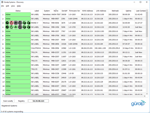
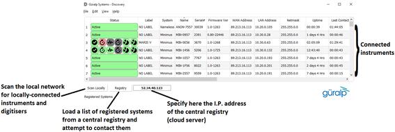
Discovery will initially “listen” for connected instruments on your local network. This mode can be refreshed by clicking the “Scan Locally” button or by pressing the short-cut keys  +
+ .
.
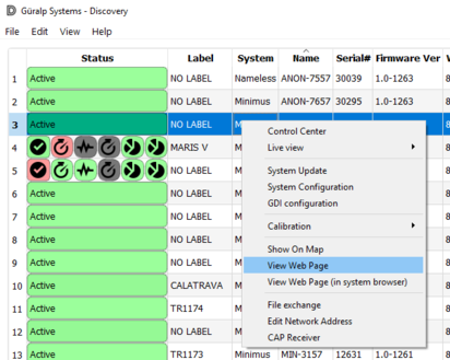
The Minimus web page can be accessed right-clicking on the instrument from the list and selecting “View Web Page”. The web-page is also reachable from a web-browser by typing the LAN IP address of the digitiser in the browser address bar.
A Maris digital instrument connected to the Minimus is defined as Instrument 1.
4.2.3 Live View
Waveform data recorded by the Minimus’ internal sensors and by the Maris sensor can be viewed using Discovery’s live waveform/data viewer.
To open the Viewer, in Discovery’s main window, select an instrument and, from the View tab in the toolbar, select “Live View”. The menu will then present three options for data streaming:
GDI and GCF channels
GDI only
GCF only
The GCF option uses the Scream! Protocol to stream data in packets of, typically, 250, 500 or 1,000 samples. The GDI protocol streams data sample-by-sample and also allows sending of instrument calibration parameters so that data can be viewed in terms of physical units.
Güralp recommends using the “GDI only” option for waveform viewing. The inherently low latency of the protocol makes it easier to perform initial testing.
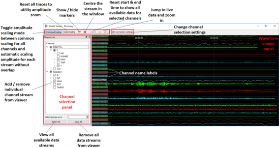
The main features of - and key buttons in - the Viewer window are shown in the screen-shot below. Basic amplitude and time zoom functions are given in the Window zoom controls panel and streams can be easily added to or removed from the Waveform viewer panel.
Note: If the Maris digital sensor is not connected to the Minimus canister, the live view may show unusual behaviour. Ensure that the sensor is connected before opening the viewer.
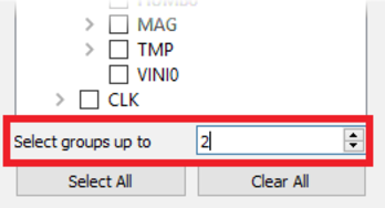
The channels are divided in groups with different hierarchical importance. The most important are the velocity/acceleration channels with higher sample rate: these belong to group 1. The least important group, group 6, includes humidity, temperature, clock operation parameters etc. When the live view is launched, only the channels in group 1 are selected. It is possible to change this setting by selecting a different group number from the “Select group up to” box highlighted in the next picture.
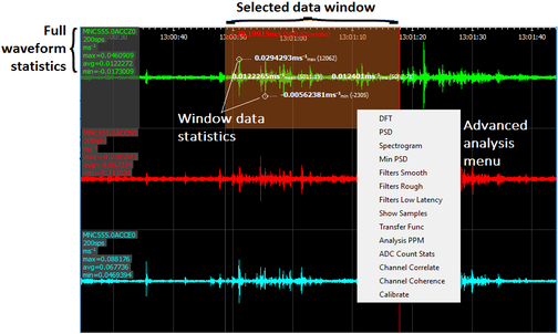
When only few channels are chosen for viewing, the channel name labels include data statistics including the maximum, minimum and average amplitudes in physical units. Also, by selecting and dragging a window of waveform data, the viewer will display similar statistics for the data within the selected window. By right-clicking on the window you can perform advanced analysis on the data, including plotting power spectral densities (“PSDs”), spectrograms and discrete Fourier transforms (“DFT”).
4.2.4 Data storage
The Minimus uses microSD (non-volatile) memory technology to store seismic data locally. The Minimus features two microSD cards to provide redundancy; this helps to protect data in the unlikely event of corruption/loss of data. One card is internal and cannot (in most circumstances) be removed by the customer; the other is hot-swappable and accessible via the screw-cap on the upper surface of the Minimus.
The Minimus will be supplied with two 64 GB (nominal) microSD cards.
The instructions on how to extract the external microSD card can be found in MAN-MIN-0001 in section “Data storage”.
Note: In the Maris systems, the Minimus is installed inside a pressure canister. It is necessary to extract the digitiser from the canister to physically access the microSD card. Recorded data, however, can be downloaded using the Ethernet link available on the MIN-K connector, avoiding opening the canister.
MicroSD cards need to be specifically formatted and initialised to operate with the Minimus. Cards supplied with Maris systems will have the correct formatting applied prior to shipping.
Data are stored on the microSD cards in the commonly-used miniSEED format. Data for each channel are saved in individual 128 MB files. These files are created empty during the initialisation procewss and then filled, one by one, with data as required. Instrument and station meta-data (e.g. instrument responses, coordinates, compression type etc.) are stored in the Dataless SEED format.
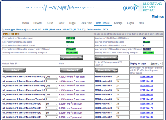
Monitoring and configuration of data storage can be found in the “Data Record” tab of instrument web page. This page is organised into three main panels: microSD status, card formatting controls and channel recording configuration.
Caution: Changes in the “Data Record” configuration will effect the system power consumption. The Minimus has been shipped with the optimal configuration for this specific project. Any Minimus firmware upgrades will erase these settings so you should save the configuration before carrying out a firmware upgrade.
The three main velocity channels can be recorded at two different sample rates, denoted by sd_consumer0 and sd_consumer1. The primary channels
sd_consumer0(Sensor1SeismoXSmooth)
(where X = Z, N or E) must have a different sample rate from the secondary channels
sd_consumer1(Sensor1SeismoXSmooth)
The MEMS accelerometer channels can also be recorded in two different sample rates. The primary channels
sd_consumer0(Sensor1AccelZRough)
must have a different sample rate from the secondary channels
sd_consumer1(Sensor1AccelZRough)
The sample rate can be selected using the drop-down menu at the right-side of each channel. An option in each prevents the associated channel from being recorded. To stop all channels from being recorded, click the  button.
Note: A reboot of the system is required in order to apply the changes; this can be done by clicking the  button.
If the same sample rate is selected for both sd_consumer0 and sd_consumer1, the reboot will automatically disable the secondary recorded stream.
Card and data recording status can be monitored in the upper-most panel of the “Data Record” tab.
The left-hand column provides details of the external (primary, removable) microSD card; the right-hand column shows the status of the internal (backup) card.
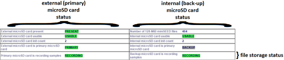
The information in this panel indicates:
Whether a card is inserted;
Whether an inserted card is usable (i.e. correctly formatted); and
Whether the card is recording data.
Note: After re-inserting an external microSD card, reload the Data Record page for the card/recording status to successfully update.
During the card re-formatting process, empty files are created. During recording, these are written to as required.
There are two methods for card reformatting: “Quick format” and “Full format”. The quick format mode should be used for pre-deployment tests (e.g. stomp or huddle tests) to ensure that the instruments are operating properly. This mode appends new data to files that contain existing data. Full formatting should be used prior to a long-term deployment to ensure that headers are included and files are fully clean before writing.
4.2.4.1 Quick format
Ensure the external microSD card is correctly inserted. Click the  button and a dialogue box will appear to confirm the formatting operation – click the “OK” button to continue. The instrument web page will refresh and return to the “Status” tab. The reformatting operation is now complete.
4.2.4.2 Full format
Ensure the external microSD card is correctly inserted. Click the  button and a dialogue box will appear to confirm the formatting operation – click the “OK” button to continue. The instrument web page will refresh and return to the “Status” tab. The reformatting operation is now complete.
4.2.4.3 Downloading recorded data
The file name is composed of three parts: channel name, sample rate and file number as below:

The description of each channel is explained in Appendix 3: Instrument/channel names on page 40.
If the web page is accessed from a web browser, clicking on the file from the list will automatically start the download, as shown below.
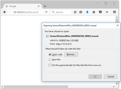
If the web page was launched from Discovery, it is necessary to copy and paste in a web browser the link URL of the file.
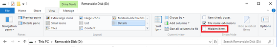
The microSD cards are formatted with empty files which are filled with data as they become available. The file-names are changed when the files are written to. Until they are written to, they are marked as “hidden” files, so that it is easier to see how many files contain data when looking at the contents of the card.
Note: When viewing files, Güralp highly recommends that Hidden files are not shown. In Windows 10, this can be done by clearing the “Hidden items” check-box within the ribbon of Windows Explorer.
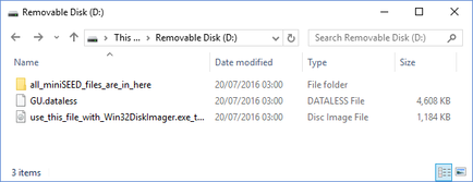
To view files saved on the external microSD card, insert the card into a microSD card reader (external or in-built) on your PC/laptop. Within a few seconds, the card should appear as a removable disk/drive.
In the root directory of the disk, there is a file named network.DATALESS where network is the two-character network code defined in Discovery (e.g. GU.DATALESS). This file is a Dataless SEED volume that contains the meta-data (http://ds.iris.edu/ds/nodes/dmc/data/formats/dataless-seed/), including instrument responses, coordinates, compression type etc. that is associated with the miniSEED data-files. The Dataless SEED is generated from the .RESP files for each channel.
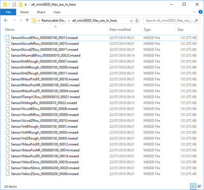
The root directory contains a directory which holds all of the recorded miniSEED files, named all_miniSEED_files_are_in_here. The file-name prefix is the same as the channel name description given in the “Data Record” tab. Each file is 128 MB in size.
The miniSEED files stored on the microSD card are displayed like this:
4.2.5 Data transmission
Monitoring and configuration of transmitted data can be found in the Data Flow tab of the instrument’s web page.
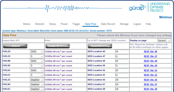
In the Output Rate SPS column, drop-down boxes are available for each channel to either prevent the channel from being transmitted (by selecting the Disabled option) or to choose the sample rate.
After changing the sample rate, the Minimus must be restarted beforr the changes come into effect; this can be done by clicking the
button.
4.2.6 GNSS lock status
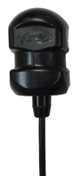 The Minimus is supplied with a new-generation compact GNSS receiver with an in-built receiver that supports the Navstar/GPS, GLONASS and BeiDou satellite constellations.
The receiver comes with an RS422 black cable that has an over-moulded 14-way LEMO connector. For the Maris OBS system, an adaptor cable is provided with a 14-way LEMO connector on one end and an 8-way male Micro Circular SubConn connector on the other end.
The LEMO connector uses a push pull latching mechanisms to provide a secure, rugged and durable connection. To insert the GNSS cable, line up the two red marks – one on the socket connector and one on male connector - then firmly push together until the connectors click into place.
Please see section 6.2 for full pin-out details.
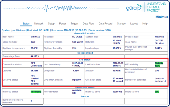
Diagnostic information is available in the “Status” tab of the instrument’s Web page. A number of GNSS reporting parameters are given, including:
Connection status
Last GNSS update (sync) & last GNSS lock date/time
GNSS Stability:
0% → no GNSS connected;
1% → GNSS connected, but waking up (this can occur if the GNSS receiver has been moved a long distance since last power-up).
2-99% → view of sky obstructed.
100% → normal operation with clear view of sky
Latitude, longitude, altitude
Horizontal dilution of precision (the accuracy of the position and time information, given the position of the visible satellites relative to receiver)
GNSS PPS status
GNSS NMEA streaming
GNSS fix state (None, 2D or 3D)
The number of available satellites (in use / in view)
The status of the GNSS timing is shown in the Status tab of the web interface
The Maris Minimus needs to be connected to the GNSS receiver before the deployment in order to both obtain the precise time and trim the internal real time clock. The GNSS should be disconnected before the installation and reconnected when the system is brought back to the surface. The absence of the GNSS during the period on the seabed will introduce an intrinsic error between the internal clock and the real timing. When the GNSS is re-connected to the digitiser, the real time clock drift will be calculated.
Caution: The calculation of drift is performed automatically. It is important that the batteries are not removed during or immediately after the recovery: wait until the GNSS subsystem reports that it is locked and the drift has been calculated.
Note: The real time clock can be affected by variations in temperature.
4.2.7 Power save mode
The Minimus digitiser provided with the Maris OBS system is able to run in “power-saving mode” in order to reduce its power consumption.
To enable it, select the option Full power-save from the Deploy mode drop-down menu in the Setup tab of the web page.
Note: This action will have no immediate effect.
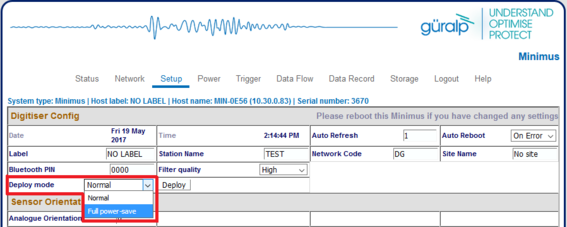
The power-save mode temporarily disables the auto-centring of the Maris digital sensor.
When this mode is selected, the Auto Center Disable option appears and allows the user to specify for how many hours the auto-centring procedure is kept disabled. This stops the instrument from being continuously re-centred during deployment.
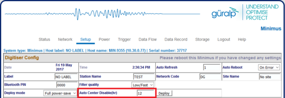
Note: The suggested safe value to input is around 10-12 hours in order to cover the overall deployment procedure.
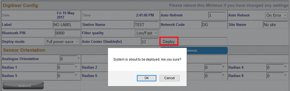
The final step is to click on the “Deploy” button and confirm or cancel the operation from the pop-up window that appears.
A thirty-second count-down will start before the system enters power-save mode. Your last opportunity to cancel the operation is to click on the Abort deployment button.
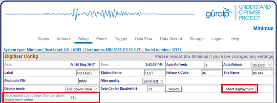
Caution: The power-save mode will disable the Ethernet and GNSS modules. Once the Ethernet module is disabled, it can only be re-enabled via a serial connection. Refer to section 4.2.8 for details.
4.2.8 Disabling power-saving mode via the serial terminal
In the unlikely event of the user experiencing problems with the operation of the Minimus or if the Ethernet module has been disabled by the “power-saving mode”, a serial diagnostics connection is available.
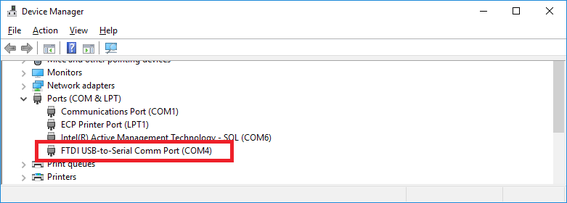
The user should plug in the 9-pin COM port of the test cable to a PC/laptop. If a 9-pin COM port is not available, a serial-to-USB converter should be used instead and connected to an available USB port. Güralp recommend converters based on the FTDI chip-set.
In order to identify the COM port to which the test cable is connected, launch Windows Device Manager. The appropriate COM port is the one that appears when the serial cable is plugged in.
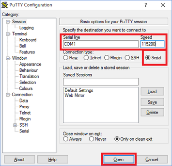
A terminal communication interface can be made using a Telnet / SSH client, such as PuTTY (www.chiark.greenend.org.uk/~sgtatham/putty/). The appropriate COM port should be entered as the “Serial line”, and the Speed should be set to 115200. Select the “Open” button and the terminal window of the Minimus should open, displaying status logs.
To disable the power-save mode and switch on the Ethernet module, type the command powersave off in the console.
More detailed command-line information can be found in the Minimus manual MAN-MIN-0001.
4.3 Radian configuration and control
Before the deployment, make sure that the Radian digital seismometer works correctly in all his features. The instrument can be configured via Discovery and using the Minimus web page.
4.3.1 Setting the long-period response
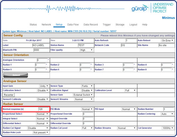
The Güralp Radian supports remote/electronic switching of the broadband sensors long-period response. This switching is carried out within the sensors’ force feedback circuit. The long-period corner frequency can be controlled from the Setup tab of the instrument web browser inside Discovery, editing the Normal response.
Note: When changing a setting in the Minimus web page, ensure that you wait for a few seconds before changing another setting. This allows time for each change to take effect.
4.3.2 Mass centring
By default, the Radian automatically keeps masses centred. The Radian’s unique motorised mass centring system allows the masses to centre when the instrument is installed at any angle.
To perform a manual centring of the masses, launch the Minimus Control Centre by right-clicking on the device in the Discovery main window.
The Radian is identified with the title Instrument 1.
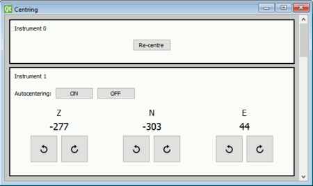
The mass position values in counts of the three components are showed in real-time under the corresponding component indicators (Z, N, E).
Click on one of the right or left button under any component in order to manually adjust the mass position.
Auto-centring is enabled by default. The auto-centring procedure consists of an initial approximate mechanical centring followed by a more accurate electrical centring sequence.
To turn off Automatic Mass Centring, select the  button in the Auto Centring option (not recommended). To restore the default setting, click on the
  button.
4.3.3 Calibration
4.3.3.1 Seismic channels calibration
Calibration is a procedure used to verify or measure the frequency response and sensitivity of a sensor. It relates the output voltage to the actual corresponding ground motion.
The Maris is a digital sensor and it calibrated once in the factory. The calibration parameters are saved in the instrument and automatically transmitted to the Minimus digitiser during each boot-up phase.
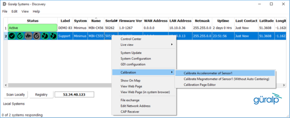
To access the Maris sensor calibration page, go to Discovery’s main screen, right-click on the instrument and select “Calibration” → “Calibration Page Editor”.
Please refer to Section 5.11.4 of MAN-MIN-0001 for full details on using the Calibration Page Editor.
4.3.3.2 Accelerometer calibration
The Maris is supplied with an internal three-axis MEMS accelerometer with a measuring range of ±2 g. The accelerometer helps to determine the Radian’s position in space (pitch and roll).
The accelerometer should be calibrated once. It is not necessary to repeat the calibration at the deployment site because the Earth’s gravitational pull can be considered sufficiently constant in each part of the world.
To calibrate the Maris accelerometer, go to Discovery’s main screen, right-click on the instrument and select “Calibration” → “Calibrate Accelerometer of Sensor1”.
In the calibration window (see below), the left-hand panel gives a three-dimensional visualisation of the Radian’s orientation (left) with respect to a fixed reference frame (right). The view can be rotated by sliding the “Viewport” bar. The labels, “F”, “B”, “L” and “R” refer to the Front (North), Back (South), Left (West) and Right (East) directions of the Radian respectively.
The right-hand side of the panel gives real-time values of accelerometer measurements, with calculated angles of pitch and roll.
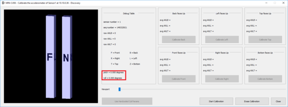
The calibration of the accelerometer is performed in six stages, one for each combination of polarity and axis of the instrument.
The North face of the Maris can be determined from where the label is attached or from the connector (the larger orientation groove points North/Front).
The Top face of the Maris is the one where the cable is connected and the Bottom face is the one with the pilot cone.
To perform the calibration follow the steps below:
Click on the Start Calibration button;
Position the Radian in horizontally with the Back facing up, click on the Calibrate Back button and wait for 15-20 seconds without moving the Maris;
Rotate the Radian and position it with the Left facing up, click on the Calibrate Left button and wait for 15-20 seconds without moving the Maris;
Rotate the Radian and position it with the Front facing up, click on the Calibrate Front button and wait for 15-20 seconds without moving the Maris;
Rotate the Radian and position it with the Right facing up, click on the Calibrate Right button and wait for 15-20 seconds without moving the Maris;
Position the Radian in vertically with the Top facing up, click on the Calibrate Top button and wait for 15-20 seconds without moving the Maris;
Rotate the Radian and position it with the Bottom facing up, click on the Calibrate Bottom button and wait for 15-20 seconds without moving the Maris;
Click on the Close button.
4.3.3.3 Magnetometer calibration
The Maris comprises an internal three-axis magnetometer that can measure the Earth’s magnetic field (in nanoTeslas) allowing the instrument to be used as a digital compass. The magnetometer can be affected by magnetic and environmental interference (including other electronic equipment), so it must be carried out at least several metres away from any electronic devices, any magnetic objects or any large metallic objects.
The magnetometer uses information from the internal MEMS accelerometer (pitch and roll) to determine the Maris position in space. The magnetometer helps to determine the Maris horizontal orientation (yaw). In addition, the magnetometer may be used to determine relative changes in the near-field magnetic field that may be caused by noise sources.
The magnetometer should be calibrated to find the direction of maximum magnetic field strength, which may be interpreted as Magnetic North. If the magnetometer is being used for this purpose, magnetic declination (http://www.ngdc.noaa.gov/geomag-web/#declination) must be accounted for to estimated the orientation of True North.
The magnetometer should be re-calibrated upon delivery of the Radian and, ideally, every time the instrument is moved to a different location, in order to account for local magnetic field variations.
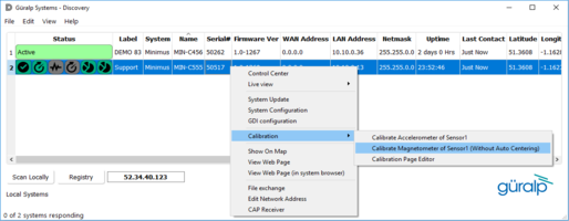
To calibrate the Maris magnetometer, in Discovery’s main screen, right-click on the instrument and select Calibration → Calibrate Magnetometer of Sensor1 (Without Auto Centring).
In the calibration window, the left-hand panel gives a three-dimensional visualisation of the Radian’s orientation (as described previously when discussing the accelerometer calibration window).
When the calibration process is started, the right-hand side of the panel gives real-time values of accelerometer and magnetometer measurements, with calculated angles of yaw, pitch and roll.
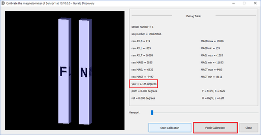
To perform the calibration, follow the steps below:
Click on Start Calibration button;
Rotate the Maris in all the possible angles. This is so that all of the faces are exposed to the maximum magnetic field present on the site.
Click on Finish Calibration button when the values on the right-side of the window stop being updated.
Click on Close button.