Chapter 5. Main form
The main form of the Network Trigger application gives an overview of what is happening in the network. The form is shown below:
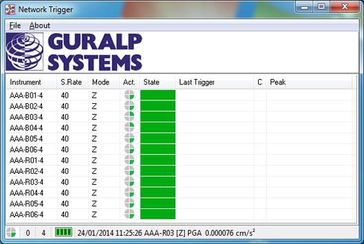
The form contains the list of instruments and some related information. At the bottom of the form, application status information is shown together with data from the last GCF data block received.
5.1 Main table
The table has eight columns containing:
the instrument ID;
the sample rate in samples per second of the data for that instrument;
which components are active for that instrument;
an activity indicator;
the operating state; and
three columns with details about the last trigger event for that instrument.
“No Proc” is displayed in the State column when data have been received for the instrument, but there is no processor configured to handle the data.
“No Cal” is displayed in the State column when there are no calibration data for the instrument. This can be because the application cannot find the calvals.txt file or because information for the specific instrument is missing from the file.
“Initialising” is displayed during the period when data is being received for the instrument and the time is still being allowed for the data for different components to synchronise and for the filters to settle down.
The Activity column (Act.) is a visual indication that data are being received for that instrument. The indicator ( ) advances each time a GCF block is received.
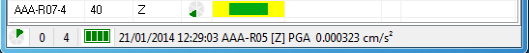
Once initialisation for an instrument is complete, the state column will contain a colour. During normal operation, the colour will be green. However, if data are not received for an instrument for a period of time, the colour will change progressively to red. Should data be received again, the central part of the colour block will return to green and the outer part will retain the colour it had before the data reception resumed, as illustrated below:
The status colours can be reset using the menu File→Reset Status Colour.
5.2 Status bar
The bottom of the form contains a status bar which displays, from the left:
a system activity indicator (
 );
);the number of triggered instruments;
the group trigger value;
relay status (
 ); and
data from the last received block of GCF data.
The system activity ( ) indicator shows that the application is operating. It should advance at a regular rate.
The relay status graphic ( ) is green when operating normally. When a relay is operated, the appropriate block in the graphic changes colour to a light green. The left-most block is an indicator for relay 1 through to relay 4 on the right. If the relay board is not detected, the graphic will be coloured red. If relays are not enabled for operation during an event, the graphic will be coloured grey.