Chapter 2. Setting up the CD24
This section gives an overview of how to set up a CD24 and begin recording data. We recommend that you set up a test digitiser in your office or laboratory as a “dry run” to gain a basic understanding of the system and to check that it is functioning as expected.
This test installation will use the digitiser's default settings. Data will be received using Güralp Systems' Scream! software, available from the website: www.guralp.com
2.1 Connectors
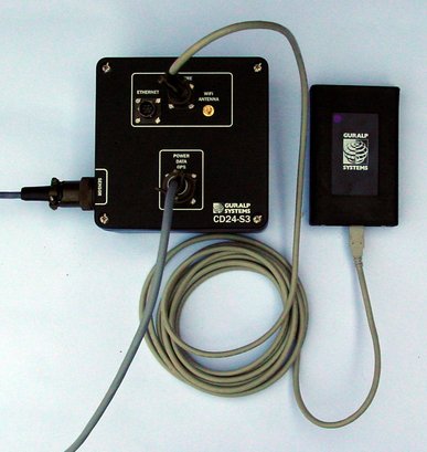
The CD24's output connectors are located on the lid. The sensor input is located on the side. The digitiser can be supplied with a number of options, so not all the connectors may be present on your digitiser. The input connector is configured to connect directly to one of GSL's sensors and has all the necessary power and control functions.
All CD24s have a 19-pin mil-spec connector on the lid for connection to a supplied breakout box with the following connections:
a 6-pin socket for connecting the supplied GPS unit;
a 10-pin plug for connecting to a PC's serial interface or a Güralp data module..
a 6-pin mil-spec plug for connecting to a power source.
You may need to attach a suitable connector to the power cable provided. The CD24 draws a nominal current of 55 mA from a 12 V supply when in use; thus, using a 12 V, 25 Ah sealed heavy-duty lead-acid battery, you should expect the digitiser to operate for more than a week without recharging.
The CD24 may also have connectors for the FireWire, Ethernet or Wi-Fi interfaces.
2.2 Test installation
To test the CD24, you will need access to a PC with a 9-pin serial port (RS232), a 12 V power source and a working sensor (e.g. CMG-3ESP, ESPC, 40T or 6T).
Install Scream! on your PC and run it.
Connect the wire from the breakout box to the CD24's 19-pin connector labelled: POWER DATA GPS.
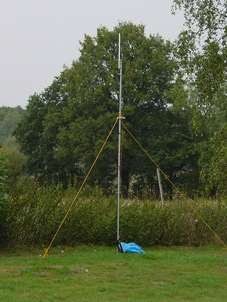
Connect the 6-pin connector on the breakout box to the GPS unit using the GPS cable. Position the GPS so that it has a good view of the sky.
Note: If you do not have a view of the sky, you can operate the CD24 without a GPS unit, but timing information may be inaccurate.
Connect the sensor to the 26-pin connector on the side of CD24.
Connect the 6-pin data plug on the breakout box to the 9-pin serial port on your PC using the serial cable.
Use the power cable to connect the 10-pin power plug on the breakout box to a fused 10 – 28 V power source.
The CD24 and instrument are now fully operational and will already be producing data.
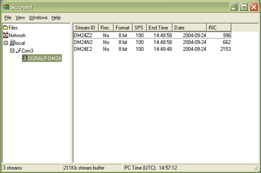
After a few seconds, you should see the CD24 digitiser appear under Network – Local – COM1 in the left-hand panel of Scream!'s main window. (If your PC has multiple serial ports, it may appear under some other COM port name.) Soon after, data streams will begin appearing in the right-hand panel. Streams with higher sample rates will appear sooner than those with lower sample rates:
If this does not happen, check all connections, and ensure the power supply is providing the correct voltage and current.
Each data stream has a Stream ID, a six-character string unique to it. Stream IDs normally identify the instrument, component and sample rate of each stream. Thus the stream 1026Z2 refers to a Z-component stream from instrument 1026, at tap 2. For more details on taps and sample rates, see section 3.1.2, page 27.
Data streams ending in 00 are status streams containing any extra information sent from the digitiser.
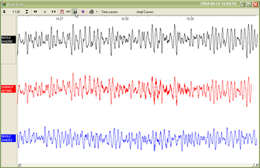
To view data, select a stream and then double-click to open a Waveview window.
You can view several streams at once by holding down SHIFT as you select, and then double-clicking the selection.
To start recording new data to a file, right-click on a stream or a selection of streams and choose Start recording from the pop-up menu. Recording settings, directories, etc., can be altered by selecting File → Setup... from the main menu and switching to the Recording tab.
To view status information, select the stream and right-click to open a pop-up menu. Select View.
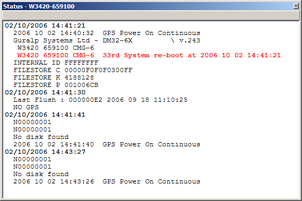
The first few status blocks will consist of the CD24's start-up messages, including its software revision number and the data streams selected for downloading and triggering.
Later blocks give information on the GPS system (number of satellites visible, the location of the GPS antenna, time synchronization status, etc.) and the baud rates in use for each channel.
For more information on SCREAM! refer to the user manual available from the Güralp Systems' website: www.guralp.com
2.3 Setting up the Ethernet or wireless interface
CMG-CD24 digitisers with Ethernet or Wireless features installed use an embedded Lantronix Wi-Port module to provide the network interface. Configuration of the Ethernet or Wireless interface is made using the Lantronix' DeviceInstaller utility for Microsoft Windows, using a DHCP server or the via the serial port. You will need a PC with a network or wireless interface installed or an RS232 connector,
You may find it easiest to gather together all the Wi-Fi hardware before taking it into the field and configuring it from a local wireless-enabled PC.
There are two types of wireless network topology supported by the Wi-Port.
Infrastructure networks need additional hardware, such as wireless access points and routers, to work. Any host on the wireless network will communicate with the access point or router, which manages all the connections and ensures data are transmitted correctly. This device may also provide connectivity to the Internet or your local network.
Ad hoc networks can be set up with no additional hardware. Each host on the wireless network attempts to communicate directly with the other hosts. Ad hoc networks are easy to set up, but they are only suitable with a small number of hosts. In seismic networks, infrastructure mode is normally preferred, since sensors do not need to communicate with each other. For more information see Appendix F – Setting up an “ad hoc” wireless network on page 113.
2.3.1 Using DeviceInstaller
Download and install the DeviceInstaller utility from the Lantronix Web site at http://www.lantronix.com/
DeviceInstaller also requires the Microsoft .NET framework to be installed. If you do not have this already, it can be downloaded at www.microsoft.com.
Note: DeviceInstaller will not work through routers or across the Internet. All the devices need to be on the same network segment as the PC.
Find out the MAC address of the CD24's network interface. This should be printed on a label on the case.
If the Data Out port on the breakout box is connected to anything, disconnect it.
- For Ethernet networking, connect the CD24's ETHERNET port to the the PC's network interface either using a crossover Ethernet cable or through a network hub. Note that using a hub, you can connect several CD24s to the same PC and configure them all at the same time.
NOTE: Any connection to the Data Out port on the breakout box will disable networking
For Wireless Networking configure your wireless router or access point to use a network name (SSID) of LTRX_IBSS. Disable any security features of the wireless router or access point.
Run DeviceInstaller.
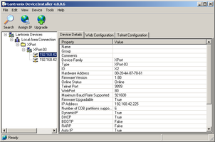
DeviceInstaller's main window has two panels, a tree on the left (with Lantronix Devices at the top) and a table on the right.
The program will automatically look for Lantronix devices on all of your computer's network interfaces. If necessary, you can narrow the selection by clicking on an entry in the tree on the left. If the program does not list the device, press F5 or use Device > Search from the menu system.
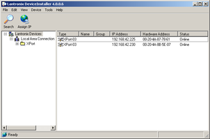
A Wi-Port entry should appear in the table on the right, denoting that a device has been detected.
If more than one Wi-Port entry appears, DeviceInstaller has detected several devices.
For every detected device, the program shows the Hardware Address (i.e. the MAC address) and the IP address it is currently using. If you are using a wireless router with a DHCP server, or an access point connected to a network with a DHCP server, the device will use DHCP to assign it an address. Otherwise, a random address will be chosen automatically.
Note: Automatic random addresses all begin with 169.254. The CD24 will choose a different one every time it is power cycled or rebooted.
The address of the CD24 may be shown in red with the status Unreachable. If this happens, the sensor and PC cannot communicate because they are not on the same subnet. Click Assign IP to start the IP configuration wizard. Follow the instructions in the wizard to set the IP address, or configure DHCP if you are using a DHCP server. When you have finished, press F5 or use Device > Search from the menu system to find the sensor with its new IP address.
Note: The IP address of the digitiser must have be on the same subnet as the computer you want to connect to. The LAN setting on the DeviceInstaller device tree identifies the IP address of your computer. The first three number groups typically need to be the same on all devices (digitisers and computer).
If you want to configure the CD24 to use a static IP address, use the Assign IP wizard as above and click Search again.
Double-click on the entry which corresponds to the CD24 you want to configure. The right-hand panel will change to show the current properties of the device.
Switch to the Web Configuration tab and click Go to open the Web configuration interface.
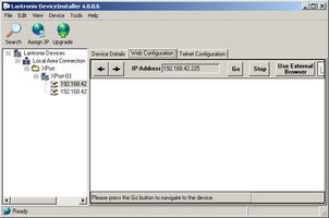
You can also click Use External Browser to use your own Web browser to configure the system.
Follow the steps at 2.3.3 to configure the module from its Web interface.
2.3.2 Using DHCP
If you cannot install DeviceInstaller on your PC, or you do not wish to, you can also get access to the CD24 using a standard DHCP server. In most cases you will need to have administrative privileges to do this.
Install and start the DHCP service on your PC.
For Ethernet networking connect the CD24's ETHERNET port to the the PC's network interface, either using a crossover Ethernet cable or through a network hub. Note that using a hub, you can connect several CD24s to the same PC and configure them all at the same time.
For Wireless Networking configure your wireless router or access point to use a network name (SSID) of LTRX_IBSS. Disable any security features of the wireless router or access point.
DHCP will not work through routers or across the Internet. All the devices need to be on the same network segment as the PC.
Monitor the DHCP server to find out what IP address it gives to each digitiser.
To configure a device, enter its IP address into a web browser.
2.3.3 Configuration with the web interface
Once you have access to the Wi-Port's Web interface, you can configure it with its proper settings.
The Web page is divided into three. A menu on the left switches between the pages of configuration options on the right. There is also a banner at the top, which tells you the current firmware revision and the MAC address.
To navigate around the Web site, click on the entries in the left-hand menu. When you have made changes to the settings on any page, save them by clicking OK before you leave the page. Once you have made all the changes click on Apply Settings to configure the digitiser.
2.3.3.1 Wireless Settings
Click on WLAN (Wireless Local Area Network) to open the WLAN Settings page.
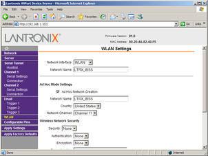
Change the Network Name (i.e. SSID) from LTRX_IBSS to a suitable name for your installation. This name will be announced to any nearby wireless devices when they search for networks.
If you are using an ad-hoc network, change the second Network Name box as well. Otherwise, deselect Ad Hoc Network Creation.
Under Wireless Network Security, set Security to WEP and configure the security parameters. If you do not do this, anyone will be able to access the CD24 and change its configuration.
Make a note of the security parameters you have used.
Click OK, followed by Apply Settings in the main menu. The Wi-Port will restart.
If you are setting up an infrastructure network, configure your wireless access point or router to use the new name and security settings, and power cycle the CD24 to make it reconnect to the network.
Reconnect your computer to the wireless network using the new name and security settings.
2.3.3.2 Configuring the serial channels
The Wi-Port has two serial channels to which you can connect. By default, these are exposed on ports 10001 and 10002.
Channel 1 (normally port 10001) is connected to a serial console (which is also exposed on the power port of the breakout box). If you have problems connecting to the CD24, you can attach a standard Güralp Systems power/data cable to this port and use Scream! to access the console.
Channel 2 (port 10002) is connected to the CD24's digital output, unless you have connected a serial data cable from the breakout box to a computer. If the breakout box is connected, the CD24 will send data streams through that interface rather than to the Wi-Port.
Click on Channel 2 – Serial Settings.
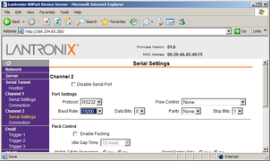
If the Baud Rate is incorrect, set it to the default of 19,200.
Note: If you change the digitiser's output baud rate in Scream! or using the terminal, you must come back to this page and change the Baud Rate setting here as well.
The remaining settings can be left at their default values. Click OK to save your changes.
For full information on the Wi-Port's configuration options, please refer to the Wi-Port documentation, which is available on the Lantronix Web site, www.lantronix.com.
When you have finished setting up the Wi-Port, apply the new settings by clicking Apply Settings. The Wi-Port will re-boot with the new settings in effect.
Note: If the Wi-Port is still using an automatically chosen random IP (beginning with 169.254), the IP address will change when you do this. You will need to go back to DeviceInstaller to find out the new IP address.
2.3.4 Installing wireless hardware
The small antenna supplied with the CD24 is adequate for initial testing or temporary installations with an access point within 50m of the digitiser.
 To send data over a larger distance, or if the line of sight between the antenna and the access point is blocked, you will need to use a larger and more powerful antenna.
In infrastructure mode, you can reduce the power requirements by using a directional antenna pointed at the location of the access point. The access point does not need to be permanently present. For example, you could set up an array of CD24 digitisers with antennas pointed towards a prominent natural feature with line of sight to all the digitisers, and access them all from this location using a laptop PC.
2.4 Configuring the digitiser
Autonomous CD24 installations will need to be configured before deployment. You can do this either
using the graphical interface provided by Scream! (see Chapter 3), or
over a terminal connection (see chapter 5).
Both methods provide full access to the configuration options of the CD24.
In particular, the CD24 can operate in a number of transmission modes. These modes determine whether the unit stores data in its on-board Flash memory, sends it over the serial link in GCF format, or does some combination of these. See section 3.2.5 for more details.
2.5 Downloading data over FireWire
The easiest way to download data over FireWire is to connect a suitable disk to the FireWire port of the CD24 and power-cycle the unit.
If you have ordered a CD24 with the powered FireWire option, you can attach the disk directly to the CD24 with no additional connections. Otherwise, you will need to connect the disk to a power source through the supplied adapter.
When the digitiser restarts, it will automatically detect the disk and flush all new data to it.
If you do not want to restart the digitiser, you can also flush data to disk manually:
Open the digitiser's console. To do this using Güralp Systems' Scream! software, right-click on the digitiser's icon (once it appears) and select Terminal.... If you are using a Güralp EAM, issue the command minicom -n port-number.
Connect a suitable disk to the FireWire port of the CD24. Provide power for the disk if necessary.
Issue the command FLUSH
This will download all data from the CD24 that it has not already transferred. If you want to transfer the entire contents of Flash memory, use the command FLUSHALL. For more details, see section 5.11.3.
Close the terminal session. If you are using Scream! or an EAM, the CD24 should start transmitting immediately. Otherwise, you may need to issue the command GO to start transferring data.
2.5.1 Reading CD24 disks
The CD24 uses a special disk format, DFD, for recording data. This format is also used by other Güralp digitisers such as the DM24.
You can read these data into a PC using Scream! or the Windows gcfxtract utilities, which are freely available from the Güralp Systems' web site. Linux and Solaris command line utilities are also available for reading data from a DFD disk.
The DFD format is not the same as that used by the Güralp Systems EAM data module, which uses either a FAT32-compatible journalling file system or an ext3 file system.
Güralp Systems can provide fully tested disks with FireWire and USB connectors. Alternatively, a third-party FireWire disk may be used (although compatibility is not guaranteed.)
2.5.1.1 Reading CD24 Disks using SCREAM!
To read a disk with Scream!:
Attach the disk to your computer. You can use FireWire, USB, or any other interface supported by your computer and the disk.
Run Scream!, and select File → Setup... from the main menu. Select the Files tab.
Set the Base Directory, Filename Format and Data Format as described above. Also, if required, set the Post-processor and Granularity options to your preference. Consult the Scream! documentation for details.
Select the Recording tab and check both Auto Record—Enable for Data Streams and Auto Record—Enable for Status Streams. Click OK.
Scream! will remember the recording options you set in steps 3 and 4 for later occasions.
Select File → Read SCSI disk... from the main menu. Scream! will search for attached disks, and open a window with a list of all the streams it has found.
Select the streams you want to replay, and click Open. The disk will appear in the left-hand pane of Scream!'s main window, and the streams you have selected will start playing into the stream buffer, as well as being recorded.
When you have finished transferring the data, if you want to reset the disk, select File → Reset SCSI disk... from Scream!'s main menu. Select the disk you want to reset, and click OK.
2.6 Receiving data in Scream!
There are several ways a CD24 digitiser can be connected to Scream!:
A direct serial connection can be made from the breakout box to your computer. This is the method we recommend for testing the digitiser (see section 2.2).
The serial port can also be used to connect an external modem. Details of how to connect modems are available on the Güralp Systems Web site.
Data can be received from the digitiser over the optional Ethernet or wireless links. Before you can do this, you will need to set up its IP address and network configuration, as described in section 2.3.
To connect to a CD24 over the network:
Run Scream!, and select Windows – Network Control from the main menu. Click on the My Client tab.
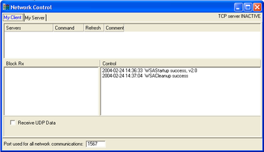
Right-click in the white panel beneath Server, and select Add TCP Server....
Input the IP address of the CD24, followed by a colon and then the output port 10002. For example:
192.168.33.2:10002
Click OK.
After a short wait, an entry for the digitiser should appear in the pane. Right-click on the entry and select Connect.
If the connection is successful, you should see blocks appearing in the Block Rx pane and streams will appear in Scream!'s main window. Close the Network Control window.