Chapter 3. Configuration & Control with Scream!
Scream! distinguishes between configuration and control of digitisers. The most important difference is that a digitiser (and its attached instrument) may be controlled through Scream! at any time while it is acquiring data, whereas configuration options only take effect after a reboot (with consequent loss of data.)
3.1 The Configuration dialogue
To change the configuration of any connected digitiser:
Locate the digitiser you want to configure. All connected digitisers have an entry in the tree on the left of Scream!'s main window. If the digitiser is transmitting data through a remote server or EAM, you may need to “unroll” the entry for that server (by clicking on the
 icon) to see the digitisers connected to it.
Right-click on the digitiser's entry (not the icon for the server or any ComXX icon). Digitisers are shown with icons depicting a coloured cylinder.
Click Configure.... Scream! will then contact the digitiser and retrieve its current configuration, a process which will take a few seconds. Once done, the Configuration setup window will be displayed.
Once you are happy with any changes you have made in the Configuration Setup window, click UPLOAD to send them to the digitiser and reboot. This will take a short while.
Note: After uploading, allow up to 1 minutes for the digitiser to re-boot and resume transmitting data.
To control a digitiser whilst it is running, either right-click on the digitiser's entry in the list and click Control..., or double-click the entry. In either case Scream! will contact the digitiser to retrieve control information and display the Control window. The options you can control immediately are:
the type of sensor you are using
GPS power cycling options
the short-term and long-term average values for triggering (but not which streams perform the trigger, or which are output by it) (see section 3.1.3)
the length of pre-trigger and post-trigger periods
calibration signal options
mass control functions
Some of these options can also be altered in the Configuration setup window. For more information on the Control window, see section 3.2.
If you need a more powerful interface to the CD24, you can also issue commands to it directly using Scream!'s terminal mode. A terminal window is opened by right-clicking on the digitiser's entry in the list and selecting Terminal.... The digitiser will stop transmitting data while you have a terminal window open but may still store it in Flash memory (depending on the current transmission mode.)
The remaining sections of this chapter describe in detail the configuration options available for the CD24. Many of these options will also be available for other Güralp digitisers.
3.1.1 System ID
The System ID pane gives information about the digitiser and its internal software and allows you to change GPS timing parameters.
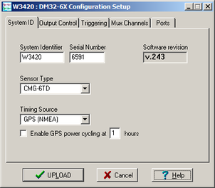
System Identifier and Serial Number : The digitiser type is identified by its system identifier and serial number. Every data and status block generated by the digitiser includes these two fields at the beginning, so that the block’s origin can be identified. On delivery from the factory, the system identifier and the serial number are set to the GSL works order number and the digitiser’s serial number, but any combination of letters A-Z and numbers can be used, such as an abbreviation of your institution’s name, etc. The system identifier can be up to 5 characters long, while the serial number cannot be longer than 4.
Sensor Type : This option tells Scream! which control commands to make available to the user. The CD24 does not require separate control commands, so you should not change this option.
GPS Type : The digitiser needs to be able to time-stamp accurately all data that passes through it. It sets its clock by receiving time signals from the GPS satellite network using an attached Trimble GPS unit. This is hard-wired into the CD24, so the GPS Type setting has no effect.
Enable GPS power cycling : If you are using a GPS unit to receive time signals, but do not experience significant drift in the system's clock (for example, in a stable-temperature environment), you can save power by selecting Enable GPS power cycling. With this option in use, the GPS time is only checked at intervals of a specified number of hours. Disabling this option keeps the GPS unit running constantly; if you have ample power, this will give the most accurate results. You can choose any whole number of hours for the interval.
3.1.2 Output control
The Output control tab allows you to select which data streams are sent to Scream! from the digitiser.
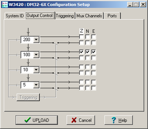
The CD24 initially samples incoming data at 2000 Hz. These data are then filtered and reduced to a lower rate (decimated) using an on-board digital signal processing unit, or DSP. The DSP has several filtering-decimation stages, which run one after the other. Stages which can produce output (and the outputs from those stages) are called taps. The CD24 can output 4 taps simultaneously.
Each configurable tap can be set to a different decimation factor by choosing values from the drop-down menus on the left. Decimation factors of 2, 4, 5, 8, and 10 are available. The numbers visible in the drop-down menu of each tap are the data rates that each of the possible decimation factors will provide, given the settings of the taps above it. Only integer (Hz) data rates are allowed: thus, for example, if one tap emits data at 25 Hz, the only possible further decimation factor is 5.
To the right of each decimation factor menu is a grid of check-boxes. These boxes mark which streams of data to generate at each sample rate. The screen shot above shows a possible configuration for a triaxial instrument. Every channel of the digitiser may be output at any tap; currently, as illustrated, all three axes are being output at Tap 2 (20Hz).
If you want to change the names used for the channels, click in the white box containing a Z in the above picture and type a letter or number. It will name the channels with a sequence of letters or numbers beginning with the one you choose (e.g. A, B, C; 2, 3, 4; 9, A, B), unless you type Z in which case they will revert to Z, N, and E.
Each combination of channel and tap has two check-boxes. The upper check-box of each pair activates continuous output, whilst the lower activates triggered output. In the example above, the digitiser will output data continuously for all three channels at Tap 2, but never for any other taps. If you do not need all the streams to output at all rates, you should leave boxes unchecked to save communications capacity. You cannot check both continuous and triggered output for the same channel and tap.
When you enable a triggered stream, the digitiser will output data in that stream only when a particular set of trigger criteria are met. This is shown diagrammatically as data passing through a switch. In the example above, we might want the high-rate data from Tap 0 to be generated only when an event registers at some other tap. To do this, tick one or more of the lower set of check-boxes for Tap 0.
With this configuration uploaded, Tap 2 will continue to produce output at all times, but Tap 0 will also emit data whenever the trigger criteria are met. The Triggering button is now shown in red to remind you that the trigger is active.
Every checked box in this window will give rise to a data stream coming from the digitiser, which will be displayed in Scream!'s main window when Scream! first receives some data from it. Every stream is identified by a 6-character code, where the first four characters identify the digitiser, and the last two characters identify the individual stream. The first four characters are set by default to the serial number of the digitiser; you can change this on the System ID pane (see page 26) or from the digitiser's console.
3.1.3 Triggering
In its standard configuration, the CD24 outputs continuous data at a sample rate you specify. In addition to this, Güralp digitisers can run a triggering algorithm on the data they acquire. This allows you to record data continuously at a relatively low sample rate, but record at a much higher sample rate during short periods when the trigger is active. The parameters controlling the triggering algorithm, and controlling the data output once the system is triggered, are all selectable by the user, permitting maximum flexibility of operation and the most efficient use of available storage space.
The CD24 can be set up for triggered output, that is, to output certain data streams only when a particular trigger criterion is met. The trigger criterion can be tested with data from the same or some other stream. For example, you could use a later tap (with a lower sample rate) as a trigger for output from an earlier, more detailed tap. Scream! 4 (and above) also allows you to configure each digitiser to receive triggers from other digitisers.
To create a new stream with a trigger, open Scream!'s Digitiser configuration window for the relevant digitiser and click on the Output control tab. In the Output control pane, a tap which gives rise to a triggered stream has a tick in the lower row of its grid of check-boxes. You cannot configure the trigger criteria until you have selected at least one stream to be affected by the trigger.
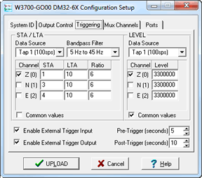
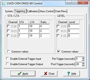
Once you have decided which streams should be output when the trigger is activated, you will be able to click on the Triggering button to describe the trigger condition. Alternatively, click on the Triggering tab at the top of the window. Either action will open the Triggering pane:
There are two triggering algorithms which Güralp digitisers can use. However, not all models can use both methods. Scream! will find out from the digitiser whether its on-board software supports each method.
3.1.3.1 STA/LTA
The STA/LTA algorithm applies a (simple short-term average) / (long-term average) calculation to the triggering stream. It works by identifying sections of an incoming data stream when the signal amplitude increases. The purpose of taking a short term average, rather than triggering on signal amplitude directly, is to make it less likely that spurious spikes will trigger the device. Averaging also introduces an element of frequency selectivity into the triggering process.
You can select which tap is tested for the trigger from the Data source drop-down menu. The tap does not have to output data to Scream! for you to be able to use it here.
Any or all of the channels available at that tap may be used to determine a trigger. You can select which channels are considered by checking the boxes in the Channel column of the table. If any of the checked channels passes the trigger condition, the trigger will activate, and will not detrigger until all of the checked channels have fallen below their respective ratio values.
The STA and LTA columns allow you to set the intervals over which the two averages are calculated, in seconds. Typically, the time interval for the short term average should be about as long as the signals you want to trigger on, while the long term average should be taken over a much longer interval. Both the STA and LTA values are recalculated continually, even during a trigger.
The Ratio column determines by what factor the STA and LTA must differ for the trigger to be passed. Finding the ratio most suited to your needs is best done by experiment. Too high a value will result in events being missed, while too low a value will result in spurious non-seismic noise triggering the system. Like the averages, their ratio is continuously recalculated for all components. Note that none of the boxes are allowed to be empty, and so you will need to enter the new value before removing the old one. Alternatively, you can use the up and down cursor keys to change the values.
For example, setting the STA to 1 second, the LTA to 10 seconds and the Ratio to 4 would give rise to the following trigger behaviour:
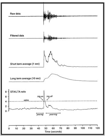
Usually, the values of the STA period, the LTA period and the Ratio will be the same for all checked channels. For convenience, Scream! will automatically fill in other values to match ones you enter. If you want to use different values for some channels, you should clear the Common values check box before altering them.
Once you have enabled the STA/LTA triggering method on a particular channel, you can use the Control window to change the values of the STA and LTA periods, together with the Ratio, without restarting the digitiser (see section 3.2.)
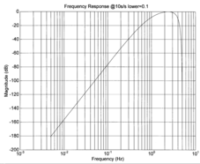
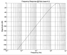
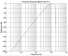
Since it is not generally advisable to trigger from broadband data, the digitiser provides a set of standard bandpass filters to apply to the data streams before they are tested for the trigger condition. This filtering serves to maximise sensitivity within the frequency band of interest, and filter out noise outside this band. You can select which bandpass filter to use from the Bandpass filter drop-down menu. The corner frequencies of the pass band of the filter are determined by the Nyquist frequency, which depends on the sample rate of the triggering data. The three filter options have pass bands between 10% and 90%, between 20% and 90% and between 50% and 90% of the data’s Nyquist frequency, respectively.
The possible filter configurations are shown in the following table:
Rate (samples/s) | Bandwidth 1 (Hz) | Bandwidth 2 (Hz) | Bandwidth 5 (Hz) |
1000 | 50 – 450 | 100 – 450 | 250 – 450 |
500 | 25 – 225 | 50 – 225 | 125 – 225 |
400 | 20 – 180 | 40 – 180 | 100 – 180 |
250 | 12.5-112.5 | 25-112.5 | 62.5-112.5 |
200 | 10-90 | 20-90 | 50-90 |
100 | 5-45 | 10-45 | 25-45 |
50 | 2.5-22.5 | 5-22.5 | 12.5-22.5 |
40 | 2-18 | 4-18 | 10-18 |
25 | 1.25-11.25 | 2.5-11.25 | 6.25-11.25 |
20 | 1-9- | 2-9 | 5-9 |
10 | 0.5-4.5 | 1-4.5 | 2.5-4.5 |
8 | 0.4-3.6 | 0.8-3.6 | 2-3.6 |
5 | 0.25-2.25 | 0.5-2.25 | 1.25-2.25 |
4 | 0.2-1.8 | 0.4-1.8 | 1-1.8 |
2 | 0.1-0.9 | 0.2-0.9 | 0.5-0.9 |
1 | 0.05-0.45 | 0.1-0.45 | 0.25-0.45 |
As can be seen, the filter you choose defines the set of permissible sample rates.
The spectral amplitudes for the various frequency responses available are shown in the figures below.

3.1.3.2 Level
Using the Level triggering method, a trigger is generated whenever one of the checked components reaches a certain level above the baseline.
Note: All unfiltered seismic signals will have some degree of offset - i.e. the average value will rarely be zero. It is strongly recommended that a high-pass filter is used to prevent this offset from affecting the level triggering algorithm but please be aware that the high-pass filters also affect the main outputs.
On the Output Control tab, set the Highpass filter to 100s, 300s or 1000s to alleviate any offset problems. Note that this filter is applied directly to the continuous data streams and, so, will also affect the main outputs.
On the Triggering tab, select the tap to be triggered from the Data source drop-down menu and the channel(s) to be considered from the Channel column of the table.
The values in the Level column are the number of counts above the baseline that channel must reach before a trigger is generated. The values are determined from the Details window for the channel under consideration. Note that the offset must be set to zero in order to determine the real baseline value.
The Level values will be the same for each channel unless the “Common values” check-box is deselected.
Once you have enabled the Level triggering method on a particular channel, you can use the Control window to change the level at which the system triggers without restarting the digitiser.
3.1.3.3 External triggering
When a digitiser or digital sensor triggers, it can send a notification signal to connected devices. You can configure other digitisers to respond to this signal by triggering in turn. This is an option which you can specify at the time of ordering.
As an example, to instruct a stand-alone digitiser with digital trigger inputs to respond to trigger notifications generated by an attached digital sensor:
Open the Configuration setup window for the digital sensor, and check Enable External Trigger Output to make it send trigger notifications to connected devices.
UPLOAD the new configuration to the digital sensor.
Open the Configuration setup window for the digitiser, and check Enable External Trigger Input to make it listen for notifications coming from the digital instrument and record data from its attached analogue instruments when it receives one (depending on its Output control configuration.)
UPLOAD the new configuration to the digitiser,
If a digitiser has both Enable External Trigger Output and Enable External Trigger Input selected, it will record data when it receives an external trigger notification as if it had triggered itself, but it will not send that trigger notification on to other digitisers. It will only send a trigger notification if its own triggering criteria are satisfied.
3.1.3.4 Pre-trigger and post-trigger recording
In order to capture all of a seismic event, it is often useful to be able to record data immediately preceding the trigger. Güralp digitisers have an internal buffer of some seconds which allows these data to be added to the triggered stream. Pre-trigger data are particularly useful for emergent-type signals, where the system does not trigger until one phase after the first arrival. In addition, to ensure that the coda of each event is included, some seconds of data are recorded after the trigger condition has ended.
The two boxes at bottom right of the Triggering pane allow the user to set the pre-trigger and post-trigger data intervals, in seconds. These values determine the minimum length of time during which data will be saved before the trigger condition occurs, and after it has lapsed. Regardless of the intervals chosen, the data in the triggered streams will begin on a whole second.
3.1.4 Mux channels
The CD24 provides a range of slow-rate auxiliary channels for reporting the system's state of health and other diagnostic information, known as multiplexed (“Mux”) channels. The number of Mux channels depends on the model and configuration of your digitiser. Generally, three channels are used to report the sensor mass position, and another measures the internal temperature of the digitiser. In addition to these, up to 12 Mux channels may be supplied for the user's own purposes. Some digitisers have a separate AUXILIARY port which can be used as input for these channels.
The collection and transmission of Mux channels is controlled using the Mux Channels pane:
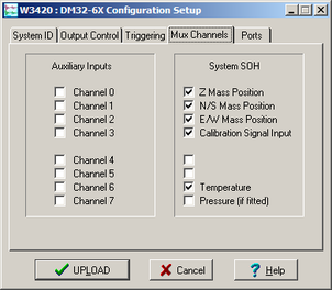
If a tick is placed in the box next to a channel, its data will be collected and transmitted as a data stream in GCF format, just as with the normal data channels. To indicate that the data come from a Mux channel, the Stream ID will take the form ****MX, where M stands for Mux and X is a hexadecimal integer (i.e. 0 – 9, and A – F for 10 through 15). The Z, N/S and E/W Mass Position Mux channels appear as M8, M9 and MA respectively.
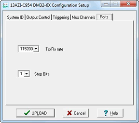
3.1.5 Ports
The Baud Rates pane of the Configuration setup window allows you to program the baud rate and stop bits for the CD24's output port.
If you have a CD24 with Ethernet or Wi-Fi options, the settings you configure here are used both on the standard data output port and on the internal port which sends data to the Ethernet/Wi-Fi module. If you change them, you will also need to configure the Ethernet/Wi-Fi module to receive data with the new settings. This can be done using the Lantronix DeviceInstaller utility (see section 2.3 on page 13).
The baud rate you choose must satisfy two conditions:
It must be high enough to allow the transmission of all data generated by the digitiser at the sampling rates you have chosen. For three streams of data at 100 Hz, for example, 9600 baud will usually be sufficient. If you wish to transmit 200 Hz data, however, the baud rate must be at least 19200.
It must be low enough to fit within the operating range of the telemetry equipment you are using. While modern modems often offer transfer rates up to 56kbaud, the telephone or transmission lines may not support these rates. The same holds true for radio telemetry.
Usually, the transmit and receive rates of the data port will be the same. If not, you may select different data rates by removing the tick in the check-box marked Identical TX/RX rates.
The Stop Bits option allows you to choose whether the serial link uses 1 or 2 stop bits. In most cases this can be left at 1, although 2 may be required if you are sending data over ‘difficult’ transmission lines (for example, some types of radio link). Using 2 stop bits will add a 10% overhead to the data.
You will also need to set the data rate for Scream's local serial port, as well as for the EAM or other communications device (if you are using one). In Scream!, you can configure a serial port by right-clicking on the serial port's icon (not that of the digitiser) and selecting Configure... from the pop-up menu. For more details, consult the online help or user guide for Scream!. If you are using an additional communications device, you should consult its documentation to learn how to set its baud rate.
3.2 The control dialogue
To control a digitiser while it is running, either right-click on the digitiser's entry in the list to the left of Scream!'s main window (not the Local or COMXX icons) and click Control..., or simply double-click the entry. Scream! will then contact the digitiser and retrieve its current status, a process which will take a few seconds, after which the Control window will be displayed. Once you are happy with any changes you have made in the Control window, click Apply to send them to the digitiser, where they will take effect immediately.
3.2.1 System

When the Control window is first opened, it will be showing the System pane.
Sensor Type : This option tells Scream! which control commands to make available to the user.
If you change the Sensor Type, you may have to Apply the change, close the Control window, and open a new one to access the Mass Control options.
Enable GPS power cycling : If you are using a GPS unit to receive time signals, but do not experience significant drift in the system's clock (for example, in a stable-temperature environment), you can save power by selecting Enable GPS power cycling.
When this option is selected, the CD24 will only check the GPS time at intervals of a specified number of hours.
3.2.2 Triggering
The Triggering pane is very similar to the corresponding pane of the Configuration setup window, although not all options are available since some require rebooting the digitiser. See section 3.1 for more details.
3.2.3 Calibration
You can check that your instrument is correctly calibrated by injecting known signals into the sensor's feedback loop. The Calibration pane allows you to do this.
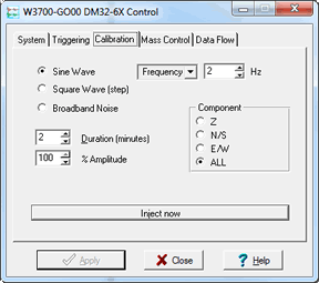
Each channel calibrates the corresponding component of the instrument. Select one or all components for calibration.
On three-channel digitisers, the calibration signal is digitised at a slower rate and returned as a Mux channel (see above) ending MB. On eight-channel models, it is returned as a full speed channel ending Xn, where n is an integer specifying the tap (as for the normal outputs).
The Duration box tells the digitiser how long to provide the calibration signal before disconnecting. This avoids the system being inadvertently left in calibration mode. The default is 2 minutes. If you change this setting, it will revert to the default value after one calibration stage.
All Güralp digitisers can produce either sine-wave or square-wave (step) calibration signals; newer models can also carry out broadband noise calibration. The Sine wave calibration signal always starts and stops on the zero crossing. The frequency or period is specified in the boxes at bottom left. Only integers between 1 and 10 may be specified for either frequency or period, so to generate a 0.5 Hz signal you should select Period and set the time to 2 (seconds). Likewise, if you require a 0.25 second period you should select Frequency and set the rate to 4 (Hz). In this manner, you can select frequencies ranging from 0.1 to 10 Hz (10 to 0.1 s periods).
You can specify step calibration by selecting the Square wave button. The square wave consists of a positive step at the start of the next minute of the digitiser’s internal clock, followed by a negative step after a specified number of minutes. After a further delay of the same number of minutes, the calibration signal is disconnected. The default is 2 minutes. The Period and Frequency are ignored.
The Broadband Noise calibration signal consists of a constant stream of white noise, which lasts for the specified number of minutes. The Period and Frequency are ignored.
3.2.4 Mass control
If supported by the instrument, the CD24 can initiate locking, unlocking, or centring of the mass. If the instrument does not support locking, unlocking and centring, instructing the CD24 to “centre” switches the instrument into a one-second response mode, which allows you to monitor the mass positions more easily.
You can issue this instruction from the Mass Control tab:
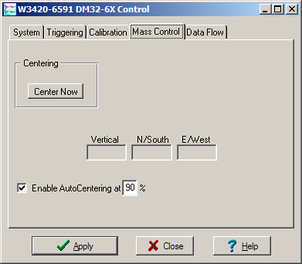
To switch into one-second response mode, click Centre.
3.2.5 Data flow
The CD24 operates in one of several transmission modes. These modes relate to how the unit uses its Flash memory:
as a simple data store, from which you can request data (FILING, DUAL and DUPLICATE modes);
as a buffer holding unacknowledged blocks, which are transmitted in preference to real-time data (FIFO mode); or
as a buffer holding unacknowledged blocks, which are transmitted whenever the channel is free but no real-time data blocks are ready (ADAPTIVE mode).
not at all (DIRECT mode).
Separate from these modes are buffering modes, which tell the unit what to do when its Flash memory becomes full: either
carry on, overwriting the oldest data held, or
stop writing and switch the CD24 into DIRECT mode.
You can switch between transmission modes in Scream! by right-clicking on the digitiser and clicking on Control..., then navigating to the Data Flow pane:
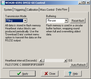
To choose a transmission or buffering mode, select options from the Transmission Mode or Buffering drop-down menus, and click Apply. Clicking Apply in this window immediately activates the transmission mode you have selected - there is no need to reboot.
An explanation of the chosen mode is displayed beneath each menu. The following sections also explain the filing modes available.
The Buffering legend also displays the amount of Flash memory present in your digitizer.
To clear the Flash memory of the digitizer, click the Reset-Flash button. You will be asked for confirmation before the memory is cleared.
At the bottom of the tab is a line describing the current state of the digitizer's memory pointers. You can use this line to check that data is being written into memory. Select Auto-Refresh to make the line update automatically.
If you prefer, you can use the CD24 terminal to switch between transmission modes. The commands to use, which take effect immediately, are given below.
3.2.5.1 DIRECT
Syntax: DIRECT

Instructs the digitizer not to use Flash memory for storage. Instead, all data is transmitted directly to clients. A digitiser in DIRECT mode still honours the GCF Block Recovery Protocol: a temporary RAM buffer always holds the last 256 blocks generated, and if a client fails to receive a block it can request its retransmission.
If you expect breaks in communication between the digitiser and its client to last more than 256 blocks, or if you want the digitiser to handle breaks in transmission (rather than relying on the client to request missed blocks), you should use
ADAPTIVE mode, if you want data to stay as near to real time as possible (but do not mind if blocks are received out of order) or
FIFO mode, if you need blocks to be received in strict order (but do not mind if the digitiser takes a while to catch up to real time.)
3.2.5.2 FILING
Syntax: FILING
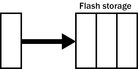
Instructs the CD24 not to transmit blocks to clients automatically, but to store all digitised data in the Flash memory. If you have chosen the RECYCLE buffering mode (see below), the memory is used in circular fashion, i.e. if it becomes full, incoming blocks begin overwriting the oldest in memory. If the WRITE-ONCE mode is active, the digitiser will switch to DIRECT mode (see above) when the memory becomes full.
You can retrieve blocks from a digitiser in FILING mode by connecting to its terminal interface and issuing commands such as FLUSH, or through Scream! (see below).
3.2.5.3 Heartbeat messages
When in FILING mode, a digitiser transmits “heartbeat” messages over its data port. These short messages take the place of data blocks, and ensure that programs such as Scream! know that a digitiser is present.
You can change the frequency of heartbeat messages from Scream!'s Control window, or with the command HEARTBEAT.
You can tell Scream! to download new data automatically whenever it receives a heartbeat message from a digitiser in FILING mode. This is useful, for example, in autonomous installations connected by intermittent modem links. To enable this feature:
Choose File → Setup... from Scream!'s main menu, and navigate to the Recording pane.
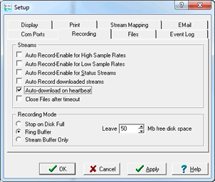
Check Auto-download on heartbeat.
Click OK.
Using FILING mode with Auto-download on heartbeat ensures that Scream! receives all new data whenever it can, regardless of the configuration of any devices between you and the digitiser.
3.2.5.4 DUPLICATE
Syntax: DUPLICATE
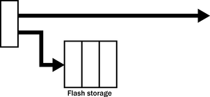
Instructs the CD24 to transmit streams directly to clients as well as storing all data into Flash storage as for FILING mode.
A digitiser in DIRECT mode still honours the GCF Block Recovery Protocol: a temporary RAM buffer always holds the last 256 blocks generated, and if a client fails to receive a block it can request its retransmission.
If you expect breaks in communication between the digitiser and its client to last more than 256 blocks, or if you want the digitiser to handle breaks in transmission (rather than relying on the client to request missed blocks), you should use
ADAPTIVE mode, if you want data to stay as near to real time as possible (but do not mind if blocks are received out of order) or
FIFO mode, if you need blocks to be received in strict order (but do not mind if the digitiser takes a while to catch up to real time.)
3.2.5.5 FIFO (First In First Out)
Syntax: FIFO
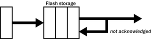
Instructs the CD24 to begin writing blocks to Flash memory as for FILING mode, but also to transmit data to clients. Data are transmitted in strict order, oldest first; the CD24 will only transmit the next block when it receives an explicit acknowledgement of the previous block.
If the communications link is only marginally faster than the data rate, it will take some time to catch up with the real-time data after an outage. If you want data to be transmitted in real-time where possible, but are worried about possible breaks in communication, you should use ADAPTIVE mode instead.
FIFO mode will consider a data block successfully transmitted once it has received an acknowledgement from the next device in the chain. If there are several devices between you and the digitiser, you will need to set up the transmission mode for each device (if applicable) to ensure that data flow works the way you expect.
Like all the transmission modes, FIFO mode does not delete data once they have been transmitted. You can still request anything in the Flash memory using Scream! or over the command line. The only way data can be deleted is if they are overwritten (in the RECYCLE buffering mode, see below) or if you delete them manually.
3.2.5.6 ADAPTIVE
Syntax: ADAPTIVE
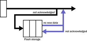
Instructs the CD24 to transmit current blocks to clients if possible, but to store all unacknowledged blocks in the Flash memory and re-send them, oldest first, when time allows. ADAPTIVE mode is best suited for “real-time” installations where the link between digitiser and client is intermittent or difficult of access.
If the communications link is only marginally faster than the data rate, it will usually be busy transmitting real-time data. Thus, it may take a while for the digitiser to work through the missed blocks. In this case, and if your client supports it, you may prefer to use the Block Recovery Protocol to request missed blocks where possible.
Some software packages (most commonly Earthworm) cannot handle blocks being received out of time order. If you are using such a package, ADAPTIVE mode will not work, and may crash the software.
3.2.5.7 DUAL
Syntax: DUAL
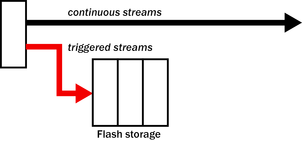
Instructs the CD24 to transmit continuous streams directly to clients as for DUPLICATE mode, but to store triggered data only into Flash storage.
If you choose DUAL mode but do not select any continuous streams for output, the digitiser will send heartbeat messages as for FILING mode. Scream! can pick these up and download new data as necessary.
3.2.6 Buffering modes
3.2.6.1 RE-USE / RECYCLE
Syntax: RE-USE
Instructs the CD24 to carry on using the current filing technique when the Flash memory becomes full, overwriting the oldest data held. This buffering mode is called RECYCLE in Scream! and on the DCM.
For example, in DUAL mode with RECYCLE buffering, the latest continuous data will be transmitted to you as normal, and the latest triggered data may be retrieved from the Flash memory using Scream! or the command line. However, if you do not download data regularly from the Flash memory, you may lose older blocks. This mode thus lets you define the end point of the data held by the digitiser.
3.2.6.2 WRITE-ONCE
Syntax: WRITE-ONCE
Instructs the CD24 to stop writing data to the Flash memory when it is full, and to switch to DIRECT mode automatically.
For example, in FIFO mode with WRITE-ONCE buffering, the station will transmit data to you continuously, but also save them in the Flash memory until it is full. Once full, the digitiser will switch to DIRECT mode and continue transmitting, though no further data will be saved. This mode thus lets you define the start point of the data held by the digitiser.
3.3 Digitiser status streams
All Güralp digitisers have a separate stream for reporting information about the system, such as their GPS and time synchronization status. This status information is in plain ASCII text format.
To see a Status window for any digitiser, double-click on the Stream ID xxxx00. This stream always has a reported sample rate of 0 samples/s.
During boot-up each unit reports its model type, firmware revision number, its System ID and serial number. This information is followed by the number of resets that have occurred and the time of the latest reboot from its internal clock. The following lines report the current configuration of the unit's sample rates, output taps, and baud rates. A typical digitiser re-boot status message looks like this:
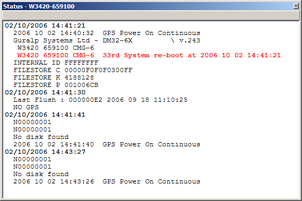
The system will produce a similar status message whenever it is powered up, and whenever you reboot it (normally, after changing its configuration.)
3.3.1 GPS
If a GPS unit is fitted, its operational status is reported on reboot and the behaviour of the time synchronisation software will also be shown.
From a cold start, GPS will initially report No GPS time together with its last position (taken from the internal backup.) All messages from the GPS that involve a change of its status are automatically reported. Repeated status messages are not shown to avoid unnecessary clutter.
This report shows the satellites the system has found, and their corresponding signal strengths.
If the system has not been moved from its previous location, it should be able to find enough satellites to obtain an accurate GPS time fairly quickly; if the GPS receiver has difficulty finding satellites, there may be a delay of several minutes before a new message is displayed.
Before beginning, the digitiser's internal time synchronisation software will wait for the GPS unit to report a good position fix from at least 3 satellites, for at least 6 consecutive messages. Messages are normally received every 10 to 20 seconds.
The system will then set the internal clock and re-synchronise the Analogue to Digital Converters so that the data are accurately time-stamped to the new reference. Any data transmitted up to this point will be stamped with the time from the internal backup clock, which is set to the new accurate time at the end of this process. The re-synchronisation will result in a discontinuity in the data received.
From this point, the control process will attempt to keep the internal time-base synchronised to the GPS 1 pulse per second output, by adjusting a voltage-controlled crystal oscillator. First it alters the voltage control to minimise the error. Next it attempts to minimise both the “phase error” (i.e. the offset between the internal 1 Hz signal and the GPS) and the drift (the frequency error relative to GPS.) During the control process the system reports the measured errors and the control signal applied, as a PWM (Pulse Width Modulation) value.
During the initial, coarse adjustment stage only the coarse voltage control is used and no drift calculation is made. If the system is operating in a similar environment to that when the system was last powered (most importantly, the same temperature) the saved control parameters will be appropriate and the system should rapidly switch to the ‘fine’ control mode. The system reports its control status and parameters each minute, with error measurements given in nominal timebase units. In a stable temperature environment the system should soon settle down showing an offset error of only a few thousand (average error < 100 microseconds) and a drift rate under 100 counts (< 1 in 10-6).