Chapter 7. Appendices
7.1 Appendix A - InfoBlocks
The CD24 has a 1kb buffer inside its firmware memory which can be used to store information about attached sensors. Users are free to store any data they wish in the digitiser's InfoBlock (information block).
Typically, this is used to store calibration parameters, poles and zeroes, etc. Newer digital sensors have their calibration information pre-loaded into the information block, in the format described below. Software applications, such as Scream!, can read the information and use it to display values using physical units rather than counts.
Information about viewing and uploading digitiser information blocks using Scream!'s graphical user interface can be found on our website at www.guralp.com/articles/20071012-howto-upload-infoblock but, if Scream! is not available, InfoBlocks can be loaded from the digitiser command line using the LOAD-I command, as described in section 5.2.4.
7.1.1 Format of the default information block
The calibration information begins with the line [instrument-id]. The instrument-id is formed from the system ID and stream ID (serial number), separated by a dash, e.g. GURALP-DEMO. It is also the string which identifies the digitiser in the lefthand pane of Scream!. This information is not actually used by the digitiser or by Scream!, but is included for consistency with the calvals file and other utilities (see www.guralp.com/articles/20060818-howto-scream-scaling and the Scream! manual for information about the calvals file).
After the identifier, calibration information is stored in the form FIELD=VALUE, with one field on each line. The fields used are shown below:
Field | Value |
Serial-Nos [optional] | An optional serial number to be displayed in the title of Scream! graphs. |
VPC | The sensitivity of the Z, N/S, and E/W digitiser input channels, in μV per count, separated by commas. These are given on the digitiser calibration sheet. |
G | The gain of the Z, N/S, and E/W sensor components, separated by commas. For velocity sensors, the gain, or sensitivity, is given on the sensor calibration sheet in V/ms-1. The gain of an accelerometer is expressed on its calibration sheet in V/ms-2. Because the outputs are differential, these are written as “2 × single-ended-sensitivity”. Most set-ups (including all those using DM24mk3 and CD24 digitisers) will use the doubled value, but older integrated instruments combining a DM24mk2 with a sensor will use only the single ended sensitivity value. |
COILCONST | The coil constant for the Z, N/S and E/W sensor components, in A/ms-2, separated by commas. These are given on the sensor calibration sheet. For a CMG-5T accelerometer, the values are all set to unity; use COILCONST=1,1,1 for these. |
CALRES | The value of the calibration resistor, in Ω, as given on the sensor calibration sheet. For a CMG-5T, use CALRES=1. |
CALVPC | The sensitivity of the digitiser's calibration channel, in μV per count, as given on the digitiser calibration sheet. Older CMG-5TD instruments do not have calibration input facilities, and thus CALVPC can be omitted. |
GRAVITY | The local acceleration due to gravity at the installation site, in ms-2. This field is used by Scream! to display streams in physical units. By default, a standard average g value of 9.80665 ms-2 is used, but this field can be changed for greater accuracy if desired. |
TYPE [optional] | The model number of the instrument, used for display purposes. |
RESPONSE | A string describing the theoretical response of the instrument, in the form response-type unit. See the table below for the correct values. |
7.1.2 Response codes and units
Instrument description | Response type | Unit |
CMG-3T (30s–50Hz) | CMG-3_30S_50HZ | Vel |
CMG-3T (60s–50Hz) | CMG-3_60S_50HZ | Vel |
CMG-3T (100s–50Hz) | CMG-3_100S_50HZ | Vel |
CMG-3T (120s–50Hz) | CMG-3_120S_50HZ | Vel |
CMG-3T (360s–50Hz) | CMG-3_360S_50HZ | Vel |
CMG-3T (120s–100Hz) | CMG-3_120S_100HZ | Vel |
CMG-3TB (30s–50Hz) | CMG-3B_30S_50HZ | Vel |
CMG-3TB (100s–50Hz) | CMG-3B_100S_50HZ | Vel |
CMG-3TB (120s–50Hz) | CMG-3B_120S_50HZ | Vel |
CMG-3TB (360s–50Hz) | CMG-3B_360S_50HZ | Vel |
CMG-3TB (360s–100Hz) | CMG-3B_360S_100HZ | Vel |
CMG-3V (30s–100Hz) | CMG-3V_30S_100HZ | Vel |
CMG-40T (1s–100Hz) | CMG-40_1S_100HZ | Vel |
CMG-40T (2s–100Hz) | CMG-40_2S_100HZ | Vel |
CMG-40T (10s–100Hz) | CMG-40_10S_100HZ | Vel |
CMG-40T (20s–50Hz) | CMG-40_20S_50HZ | Vel |
CMG-40T (30s–50Hz) | CMG-40_30S_50HZ | Vel |
CMG-40T (60s–50Hz) | CMG-40_60S_50HZ | Vel |
CMG-40T (100s–50Hz) | CMG-40_100S_50HZ | Vel |
CMG-5T (DC–100Hz) | CMG-5_100HZ | Acc |
CMG-6T (1s–100Hz) | CMG-6_1S_100HZ | Vel |
CMG-6T (2s–100Hz) | CMG-6_2S_100HZ | Vel |
CMG-6T (10s–100Hz) | CMG-6_10S_100HZ | Vel |
CMG-6T (30s–100Hz) | CMG-6_30S_100HZ | Vel |
7.1.3 Example files
The calibration information for a CMG-3T weak-motion velocity sensor might look like the following:
[GURALP-DEMO]
Serial-Nos=T3X99
VPC=3.153,3.147,3.159
G=1010,1007,1002
COILCONST=0.02575,0.01778,0.01774
CALVPC=3.161
CALRES=51000
TYPE=CMG-3T
RESPONSE=CMG-3_30S_50HZ Vel
GRAVITY=9.80122
CMG-5T accelerometers use 1Ω calibration resistors, and their coil constant is set to unity. For example:
[GURALP-CMG5]
Serial-Nos=T5585
VPC=2.013,2.028,2.036
G=0.256,0.255,0.255
COILCONST=1,1,1
CALRES=1
TYPE=CMG-5T
RESPONSE=CMG-5_100HZ Acc
GRAVITY=9.81089
7.2 Appendix B - Setting up external triggering
Güralp digitisers and digital instruments can be supplied with external triggering capabilities installed. The external trigger system is designed for maximum flexibility: you can trigger other digitisers or your own equipment using built-in relays and any equipment may be used as a trigger source, using the built-in opto-isolator. In addition, a trigger circuit can link together any number of digitisers so that they trigger simultaneously when they receive a signal.
7.2.1 Overview
The digitiser or digital instrument has two internal components related to triggering: the trigger generator and the trigger receiver.
The trigger generator runs the triggering algorithm and determines whether a trigger has occurred. If external trigger output has been enabled, the trigger generator also operates a relay which disconnects the Trigger Out Common pin (on the POWER/DATA/GPS port) from the Trigger Out Normally Closed pin and connects it to the Trigger Out Normally Open pin. See section 7.3.1.1 for connector details.
The relay is only activated whilst the generator is active. This does not include any pre-trigger or post-trigger period, which is dealt with by the trigger receiver. A trigger signal may be as short as one second.
The trigger receiver acts upon trigger signals: normally, by recording or transmitting additional data streams. The receiver will always enable these extra streams if the trigger generator determines that a trigger has occurred. If the external trigger input has been enabled, the receiver will also act on a logic signal received on the Trigger In pin of the POWER/DATA/GPS port.
Any signal between +3 and +40 V can be used - the trigger input pins drive an opto-isolator protected by a constant-current circuit.
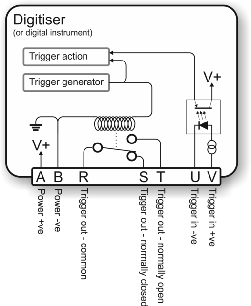
The Trigger Out relay is not activated if you provide a Trigger In voltage. The digitiser must trigger itself for the relay to switch. This arrangement prevents any trigger loops from occurring.
The diagrams on this and the following pages show the additional connections you will need to make. Pins not illustrated should be connected to your power and data systems as normal.
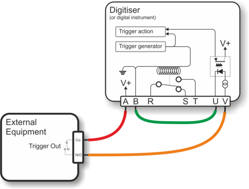
7.2.2 Using CD24 triggering to activate external equipment
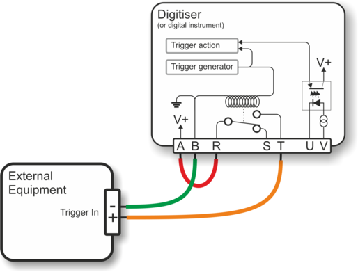
If your equipment can trigger from the same voltage as the CD24's power supply, the simplest arrangement is to use the voltage across the sensor's power supply as the trigger supply.
Connect the ground pin (B) to your equipment's trigger return line. If your equipment does not have a separate trigger return line, consult its documentation for how to apply trigger voltages. (The diagram above does not show the power supply to either the sensor or the triggered equipment: only the triggering system is shown).
Because a trigger signal may last for only a short time, using pins T and B directly to power your external equipment is not normally advisable. Ideally, the equipment should be continuously powered and listening on dedicated trigger input lines. If this is not possible, it may be enough to build a control circuit with a time-out period, which supplies your equipment with power for a suitable minimum length of time whenever a trigger is activated.
The digitiser cannot anticipate a trigger. Pre-trigger recording is achieved using a continuously-updated ring-buffer of the most recent data. Any external equipment must have its own buffering capabilities if you need pre-trigger data.
Connect pin A to pin R, and pin T to your equipment's trigger signal input.
Connect the remaining pins as normal.
If your equipment needs a different voltage, you will need to provide a separate voltage source for the triggering system. Be careful not to connect two power supplies together.
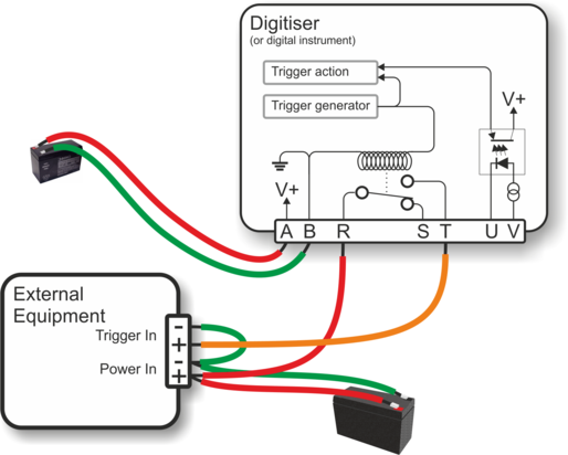
The diagram above illustrates how to trigger the external equipment using its own power supply, which is connected to the trigger input via the normally-open relay contacts (pins R and T).
In this configuration, the two power supplies are completely electrically isolated courtesy of the relay. It is normal practice, though not essential, to connect the two power supply negative terminals to a common earth point.
7.2.3 Using an external trigger source
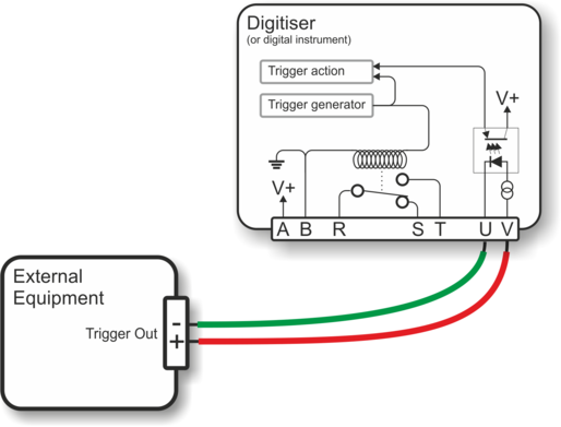
To trigger a digitiser from an external source which provides a triggering voltage, you merely need to connect the external trigger voltage to pins U and V of the digitiser as shown above. The voltage can be anywhere between 4 and 40 V DC as the constant current circuit protects the LED of the optoisolator.
If the external equipment provides a normally open relay contact, the digitiser's power supply can be used to activate the trigger input:
Connect the common pin of the relay to the positive supply on pin A.
Connect the normally open pin of the relay to the positive trigger input on pin V.
Connect the trigger input return (pin U) to the negative supply on pin B.
Connect the other pins as normal.
7.2.4 Triggering several CD24 digitisers simultaneously
A common use of the external triggering feature is to ensure that all digitisers in an array trigger at the same time. This can be achieved with the wiring layout described in this section. With this arrangement, any digitiser can generate a trigger, which will be passed on to all the digitisers in the array.
For each digitiser:
pins B (power supply ground) and U (trigger input return) of every digitiser are connected to a common ground;
pins T (trigger out, normally-open) and V (trigger in, positive) of every digitiser are connected to a common trigger line (shown in orange on the diagram);
for each digitiser, pin R (trigger out, common) is connected to the power supply positive rail via a diode (an IN4001 is suitable);
pins A and B (power supply input) are connected to individual power supplies as normal; and
the remaining data pins are connected to your recording equipment as normal.
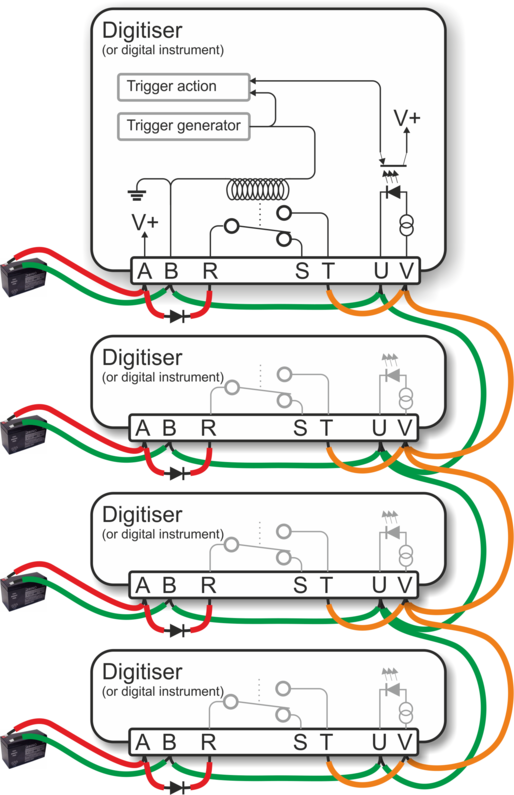
The diode between pins A and R is important, because if two digitisers generate a trigger simultaneously, their power supplies will both be connected via the internal relay contacts to the common trigger line on pins V, and hence connected together. This can cause considerable current flow with consequent risk of fire, as well as severe damage to equipment and cables.
In the case where a single power supply is used to power all of the equipment, this is not an issue and pin A should be connected directly to pin R on all units.
The more common case, where each unit has it's own power supply, is shown above. Please note that all the power supply's ground terminals will be connected together: they must, therefore, have floating outputs or grounded negative terminals.
7.2.5 Combining CD24 and DM24 digitisers in a single array
The trigger inputs of a CMG-DM24 digitiser are slightly different to those on a CD24: the return pin on the DMG-DM24 is connected internally to the power supply ground (it is isolated on the CD24).
When building mixed arrays of CD24s and DM24s (or digital instruments containing them), extra care should be taken with the interconnections. Please contact Güralp Systems Ltd. technical support for advice.
7.3 Appendix C - Connector pinouts
7.3.1 Digitiser connectors
7.3.1.1 POWER/DATA/GPS port
This is a standard 19-pin “mil-spec” plug, conforming to MIL-DTL-26482 (formerly MIL-C-26482). A typical part-number is 02E-14-19P although the initial “02E” varies with manufacturer. Suitable mating connectors have part-numbers like ***-14-19S and are available from Amphenol, ITT Cannon and other manufacturers. |
|
Pin | Function | Pin | Function |
A | Power +10 to 36 VDC | L | Isolated ground |
B | Power 0 V | M | Isolated power 0 V for GPS |
C | RS232 transmit | N | Auxiliary serial port transmit |
D | RS232 receive | P | Auxiliary serial port receive |
E | RTS | R | External trigger output link, common contact (for S and T) |
F | CTS | S | External trigger output link, normally closed contact |
G | Isolated power + 5 V for GPS | T | External trigger output link, normally open contact |
H | GPS transmit | U | External trigger input +ve |
J | GPS receive | V | External trigger input – ve |
K | GPS PPS |
Wiring details for the compatible socket, ***-14-19S, as seen from the cable end (i.e. when assembling). |
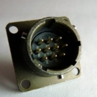
7.3.1.2 FireWire port
This is a standard 6-pin “mil-spec” plug, conforming to MIL-DTL-26482 (formerly MIL-C-26482). A typical part-number is 02E-10-06P although the initial “02E” varies with manufacturer. Suitable mating connectors have part-numbers like ***-10-06S and are available from Amphenol, ITT Cannon and other manufacturers. |
|
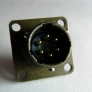
Pin | Function |
A | Power 0 V |
B | TPA +ve |
C | TPA −ve |
D | TPB −ve |
E | TPB +ve |
F | Power + V (powered FireWire option) |
| Wiring details for the compatible socket, ***-10-06S, as seen from the cable end (i.e. when assembling). |

7.3.1.3 Ethernet port
Digitisers with the Wi-Fi and Ethernet networking options have an additional 6-pin mil-spec plug (02E-10-06P) for this interface.
This is a standard 6-pin “mil-spec” plug, conforming to MIL-DTL-26482 (formerly MIL-C-26482). A typical part-number is 02E-10-06P although the initial “02E” varies with manufacturer. Suitable mating connectors have part-numbers like ***-10-06S and are available from Amphenol, ITT Cannon and other manufacturers. |
|
Pin | Function |
A | Data transmit +ve (RJ45 pin 1) |
B | Data receive +ve (RJ45 pin 3) |
C | not connected |
D | not connected |
E | Data receive –ve (RJ45 pin 6) |
F | Data transmit –ve (RJ45 pin 2) |
| Wiring details for the compatible socket, ***-10-06S, as seen from the cable end (i.e. when assembling). |
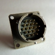
7.3.1.4 Sensor input
This is a standard 26-pin “mil-spec” plug, conforming to MIL-DTL-26482 (formerly MIL-C-26482). A typical part-number is 02E-16-26P although the initial “02E” varies with manufacturer. Suitable mating connectors have part-numbers like ***-16-26S and are available from Amphenol, ITT Cannon and other manufacturers. |
|
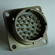
Pin | Function | Pin | Function |
A | Vertical velocity +ve | P | Calibration signal |
B | Vertical velocity –ve | R | Vertical calibration enable |
C | N/S velocity +ve | S | N/S calibration enable |
D | N/S velocity –ve | T | E/W calibration enable |
E | E/W velocity +ve | U | Centre |
F | E/W velocity –ve | V | not connected |
G | Vertical mass position | W | Unlock |
H | not connected | X | Lock |
J | N/S mass position | Y | Logic signal ground |
K | Busy indicator LED | Z | not connected |
L | E/W mass position | a | not connected |
M | Power Optional -12VDC | b | Power 0 V |
N | Signal ground | c | Power +10 to +24 V(Optional +12VDC) |
| Wiring details for the compatible socket, ***-16-26S, as seen from the cable end (i.e. when assembling). |

7.3.2 Breakout box connectors
7.3.2.1 Breakout box data port
This is a standard 6-pin “mil-spec” plug, conforming to MIL-DTL-26482 (formerly MIL-C-26482). A typical part-number is 02E-10-06P although the initial “02E” varies with manufacturer. Suitable mating connectors have part-numbers like ***-10-06S and are available from Amphenol, ITT Cannon and other manufacturers. |
|
Pin | Function |
A | RS232 transmit |
B | RS232 receive |
C | RTS |
D | CTS |
E | not connected |
F | Isolated ground |
| Wiring details for the compatible socket, ***-10-06S, as seen from the cable end (i.e. when assembling). |
7.3.2.2 Breakout box GPS port
This is a standard 6-pin “mil-spec” socket, conforming to MIL-DTL-26482 (formerly MIL-C-26482). A typical part-number is 02E-10-06S although the initial “02E” varies with manufacturer. Suitable mating connectors have part-numbers like ***-10-06P and are available from Amphenol, ITT Cannon and other manufacturers. |
|
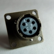
Pin | Function |
A | Isolated ground |
B | RS232 receive from GPS |
C | RS232 transmit to GPS |
D | PPS |
E | not connected |
F | Power +12 V |
| Wiring details for the compatible plug, ***-10-06P, as seen from the cable end (i.e. when assembling). |

7.3.2.3 Breakout box power port
This is a standard 10-pin “mil-spec” plug, conforming to MIL-DTL-26482 (formerly MIL-C-26482). A typical part-number is 02E-12-10P although the initial “02E” varies with manufacturer. Suitable mating connectors have part-numbers like ***-12-10S and are available from Amphenol, ITT Cannon and other manufacturers. |
|
Pin | Function |
A | 0 V |
B | +12 V DC supply |
C | not connected |
D | not connected |
E | not connected |
F | not connected |
G | not connected |
H | not connected |
J | Auxiliary serial port (RS232) receive |
K | Auxiliary serial port (RS232) transmit |
| Wiring details for the compatible socket, ***-12-10S, as seen from the cable end (i.e. when assembling). |

7.4 Appendix D - Advanced network configuration
The CD24 uses an embedded Lantronix networking module to provide Ethernet and WiFi functionality. For Ethernet-only digitisers, an 'WiPort NR' module is used. For digitisers with WiFi support, a 'WiPort' is used. Both the WiPort NR and the WiPort have serial-accessible configuration systems which can be used to configure them in the event that communication over a network is lost.
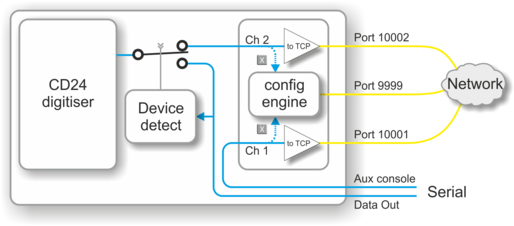
The Lantronix modules have two serial channels. Channel 2 is used for seismic data, which is typically sent over the network on TCP port 10002, although this is configurable. Channel 2 is connected internally to the CD24's data output, unless you have connected a serial data cable from the breakout box to a computer. If a device is detected on the normal serial output, the CD24 will only send data streams through “Data out” and not through the networking module. The digitiser will still be visible on the network but no data will be sent.
Channel 1 is normally unused but is exposed on the Power/Data/GPS connector (on the pins identified as “Auxilary console”). Serial data sent to this channel will be converted to TCP and sent over the network on port 10001 - please contact Güralp Systems technical support if you wish to make use of this facility.
In addition to the two data channels, you can also access two configuration interfaces via the network: a web-based configuration system and a console-based system. The console-based system is reached by using telnet to connect to TCP port 9999.
If you have problems connecting to the CD24 over a network, you can access the configuration menu over a serial link (via channel 1) by interrupting the boot process. See the following section for instructions. For full information about the WiPort NR and WiPort's configuration options, which are used during the process, please refer to the relevant documentation, which is available on the Lantronix Web site: www.lantronix.com. For the WiPort NR, the detailed documentation is at http://www.lantronix.com/pdf/WiPort-NR_UG.pdf and, for the WiPort, the equivalent document can be downloaded from http://www.lantronix.com/pdf/WiPort_UG.pdf.
7.4.1 Accessing the configuration menu via the serial Interface
Access to the configuration menu over the serial interface can be obtained using Scream! or any serial terminal emulator, examples of which are given in section 7.5. A special “Auxiliary terminal breakout cable” is required: please contact Güralp Systems technical support for details.
First, with the power to the digitiser turned off, connect the auxiliary terminal breakout cable to the PC and start the emulator. Configure the emulator for 9600 baud, 8 data bits, no parity bit and one stop bit (8-N-1), regardless of the configured settings of the networking module. Next, hold down the  key while turning on the power to the digitiser. After a few seconds, a banner will appear, showing the MAC address of the network interface, along with software and library version information. Press the Enter key to access the set-up menu. If you do not press a key, the system will proceed to boot normally.
7.4.2 Configuring the network interfaces
Once you have access to the networking module's configuration menu, you can configure it with its proper settings.
The networking module has two serial channels. Channel 1 (normally accessible via TCP port 10001) is exposed on the power port of the breakout box. (This is the channel that you are currently using if you have followed the instructions in the previous section).
Channel 2 (normally accessible via TCP port 10002) is connected to the data output of the digitiser when no other serial device is connected. It is disconnected when the digitiser detects that Scream! or a terminal emulator is connected, thus disabling data flow over the network.
During the configuration process, you are prompted, in turn, for every value in the current section. If you are unsure at any point, pressing the Enter key will retain the current value. Please note that many values need to be entered using special codes. These are all documented in the relevant Lantronix manuals.
From the main menu:
Each channel is configured individually. To configure either, enter either 1 (selecting Channel 1) or 2 (selecting Channel 2) and then press the Enter key.
Set the Baud Rate to 19200. This is the default baud rate for the CD24's digital output. If you change the baud rate in Scream! or using the terminal, you must change the Baud Rate setting here to match.
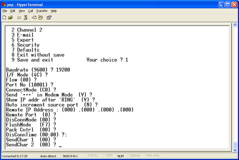
The remaining settings can be left at their default values, which is done by pressing Enter at each prompt until you are returned to the main menu.
When you have finished setting up the module, apply the new settings by selecting option 9 Save and Exit. The module will re-boot with the new settings in effect.
7.4.3 Configuring the Ethernet port
To configure the Ethernet port
If DHCP is not being used to assign IP addresses, enter the required address manually. The IP address must be set to a unique value in the network. Enter each octet and press Enter to move to the next octet.. The current value is displayed in parentheses. If you do wish to use DHCP, enter 0 at each prompt (an IP address of 0.0.0.0 is used to select DHCP operation).
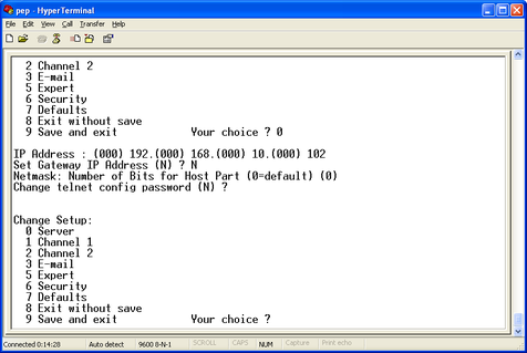
If the digitiser is to be connected to a routed network, enter the address of the default gateway in the same manner.
At the netmask prompt, enter 0 if you are using normal (classful) internet addressing. If you have a non-standard or classless addressing scheme, enter the number of bits of the IP address to be used for network identification. Note that this is not the standard way of specifying netmasks; it is more akin to the /n modifier used in CIDR address specification.
7.4.4 Configuration of the WiFi interface
If your system has WiFi capabilities, they can be configured using the same menu system.
From the main menu, select '4' and then press the Enter key to access the WiFi settings.
Configure your topology, keying 0 for Infrastructure or 1 for Adhoc mode and then press enter.
Enter the desired network name (SSID). Systems are shipped with a default SSID of LTRX_IBSS so that they can be found and configured by DeviceInstaller but you can enter any suitable value here.
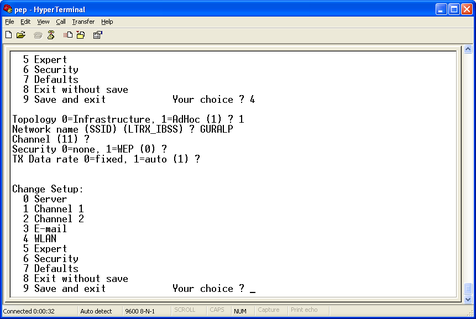
The Wifi communications channel can normally be left at its default. If you are deploying the system in an area where there are many other wireless devices, you may have to either experiment with this value to obtain reliable connections or use a wireless scanner to identify an unused (or relatively quiet) channel.
The final prompt allows you to disable or enable the security features of the wireless interface. Systems are shipped with security disabled in order to simplify access for DeviceInstaller.
7.5 Appendix E - Using third-party terminal emulators
There are a number of terminal emulator programs that you can use to access the serial ports of the digitiser and the optional networking interface. The terminal emulator built into Scream! is recommended but, if this is not available, there are a variety of alternatives. Three of these are detailed below.
7.5.1 Hyperterminal, as provided with Windows XP.
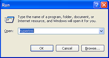
Click on “Start” and then on “Run”.
Enter 'hypertrm' and click on 'OK'.
The program will ask you for a name for the connection:
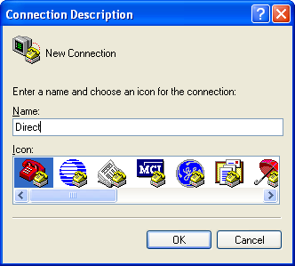
Enter any suitable name, then click OK.
You will then be prompted to enter COM port and modem details:
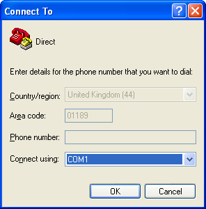
The “Country/region”, “Area code” and “Phone number” boxes can be ignored: they are only used when working with modem connections. Select the name of the correct COM port from the “Connect using” drop-down menu, then click OK. You will then be prompted to select port configuration settings:
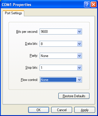
Ensure the following parameters are set:
Bits per second: 9600
Data bits: 8
Parity: None
Stop bits: 1
Flow control: None
Click on OK and the program will then connect provide you with a terminal emulator screen, from which you can access the command line of your system.
7.5.2 Using Hyperterminal with Windows Vista or Windows 7.
HyperTerminal is not provided with the Windows Vista or Windows 7 operating systems but the necessary files can copied from the i386 directory of the Windows XP CD, if you have one available. The two files you will need are:
hypertrm.dll
hypertrm.exe.
Copy the two files into your windows/system32 directory.
If you do not have a Windows XP disc the files can be downloaded from: www.mediafire.com
To access HyperTerminal, use Windows+R on your keyboard. Enter 'hypertrm' and click on OK.
Now follow the instructions given in section 7.5.1, above.
7.5.3 Using PuTTY.
PuTTY is a free terminal package for windows which is useful if HyperTerminal is not available. It can be downloaded from www.chiark.greenend.org.uk. The easiest package to use is the 'windows installer'. Install PuTTY by following the on-screen instructions.
Start PuTTY by clicking on the desktop icon or Start-menu entry and, using the “Connection type” radio buttons on the right-hand side of the screen, select the 'Serial' option.
The dialogue will change to allow you to specify the serial port and the line speed. Enter the name of the correct serial port and type “9600” in the “Speed” field:
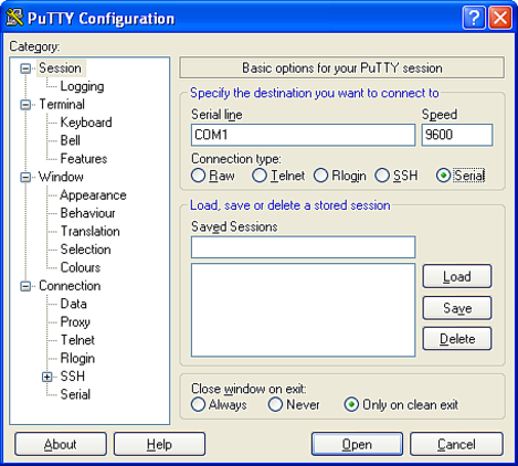
Now click on “Serial” at the bottom of the category menu on the left:
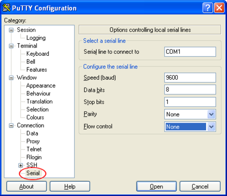
Ensure the following configurations are set:
Speed (baud): 9600
Data bits: 8
Stop bits: 1
Parity: None
Flow control: None
To save the settings, click on the 'Session' option at the top of the left-hand “Category” menu. Enter a suitable session name in the 'Saved Sessions' field then click 'Save'.
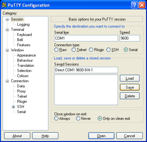
The next time you start PuTTY, your saved session will appear in the list and you can simply double-click it to open a new session with the same settings. For now, click the “Open” button to start the terminal emulator.
7.6 Appendix F – Setting up an “ad hoc” wireless network
If you do not have a wireless router or access point, you can configure your computer to set up an ad hoc wireless network when the CD24 comes within range.
To configure Windows XP to set up an ad hoc wireless network:
Open the Control Panel and select Network Connections.
Right-click on the Wireless Connection icon and select Properties. Switch to the Wireless Networks tab.
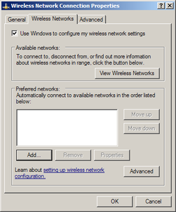
Under Preferred networks, click Advanced. Select Computer-to-computer (ad hoc) networks only.
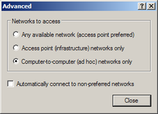
Ensure the Automatically connect to non-preferred networks box is not ticked. Click Close to return to the Wireless Network Connection Properties window.
Under Preferred networks, click Add.... Switch to the Association tab.
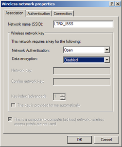
Fill in the Network name (SSID) of LTRX_IBSS
Set Network Authentication to Open and Data encryption to Disabled. Click OK.
The network connection should now be visible under Preferred networks, and in the main Wireless Network Connection window.
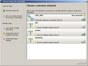
Initially, the network will be shown as Not connected.
Power cycle the CD24. After a short while, your computer should report that it has connected to the LTRX_IBSS network.
Use DeviceInstaller to find the CD24 on the new network.
If your computer is configured to obtain its network address automatically, both it and the CD24 will be using automatic random IP addresses.
Automatic random addresses all begin with 169.254. Both hosts will choose a different one every time they are power cycled or rebooted, or when the wireless network connection is lost.
To prevent this happening, configure your computer to use a static IP address, and use the Assign IP wizard in DeviceInstaller to assign a static IP address to the CD24.
7.7 Appendix G - Specifications
Outputs and response | Input range | ±10V differential |
| Nominal Sensitivity | 0.9µV/count |
| Standard output format | 24-bit |
| Noise-free resolution (NPR) at 20 samples/s | > 132 dB r.m.s. |
| Digital signal processor | TMS3200 at 144 MHz |
| Output rate | User selectable |
| RS232 baud rate | User selectable |
Physical | Operating temperature range | –10 to +75 °C |
| Case material | Die-cast aluminium |
Internal thermometer accuracy | ±0.33 °C (30 °C) | |
Internal thermometer linearity | ±0.5 °C | |
Internal thermometer resolution | 0.0625 °C | |
Dimensions | 160 x 160 x 90mm | |
Weight | 1.95kg | |
Power | Voltage requirements | 10..24V DC |
Current at 12 V DC with GPS | 165 mA |