Chapter 3. Usage
The DCM can be integrated with any system where seismic data needs to be collected, or converted from one form into another. It is designed to operate as transparently as possible, and once connected and configured for a particular role in a system it should not require further maintenance.
The rest of this chapter gives detailed installation and usage notes for several common DCM installations. Between them, they highlight many important features of the DCM. For full configuration information, please refer to the next chapter.
3.1 General notes
Stand-alone DCM modules can be supplied with a touch-screen and minibrowser as an option. This allows you to perform configuration tasks on-site. However, the touch-screen imposes some environmental restrictions on the unit.
For all other DCM units, you will need console or network access to the DCM to configure it for your installation. This is especially important if the DCM is not to be part of a TCP/IP network whilst in use.
As supplied, the DATA OUT port runs the getty service, which you can use to access the console of the DCM over a serial link. Alternatively, you can temporarily connect a computer to the NETWORK port. It is recommended that you keep a serial or modem connection to the DCM available for maintenance and troubleshooting, even if the link is too slow for general use.
3.2 The DCM as a data store
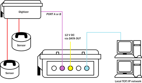
The simplest way to use a DCM is as a storage medium for digital data.
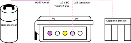
Connect the DCM to a digitizer or digital sensor.
Connect the DATA OUT port to a source of 12 V DC power.
Connect the unit to your local network as described in Section 2.4, page 15, and perform any necessary configuration of the DCM and digitizer. You will be prompted for a username and password: log in as root and use the password supplied by Güralp Systems. If you have not been given a password, use the default password rootme. You should change this password as soon as you can.
The DCM will immediately begin recording data into Flash memory as it is received, and every so often data will be moved onto the internal hard disk. At this point you can leave the DCM running without assistance.
Data is stored in the Flash memory as a number of files in Güralp Compressed Format (GCF) unless you have specified another option. Once the memory becomes 75% full, files are automatically moved to the hard disk until it is less than 50% full. (See Section 8.1, page 116, for details of the algorithm used.)
You can check that the DCM is receiving data either by monitoring the Summary page of the on-board Web interface (see Section 4.1, page ) or from a command prompt using the command
gnblocks
This command displays details about all of the DCM's serial ports, and the number of GCF blocks received so far on each one. To see information about a single port, type
gnblocks port-number
If the internal hard disk is missing or becomes full, and you have chosen the USB host option, the DCM will automatically look on the USB interface for an external USB mass storage device.
To replace the internal hard disk, unclip the cover of the DCM and hold down the lever button to bring the disk out from its housing.
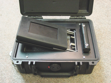
Slide the disk out and replace with another Lacie U&I drive, or any brand of IDE / USB or IEEE 1394 2.5” drive you specify (at the time of manufacture). You can do this at any time without losing data.
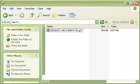
Plug the hard disk into any computer that supports the USB Mass Storage standard using a standard USB cable. Newer Linux distributions and Microsoft Windows XP have this enabled by default.
In Windows XP, you should see a series of Found new hardware messages indicating that the drive has been recognised. A new disk drive icon should appear in My Computer:

This process may take several minutes to complete.
Double click on the drive's entry to browse the files inside and copy them to your data store.
Alternatively, you can open the files directly from the USB disk using Scream! or other GCF-compatible software.
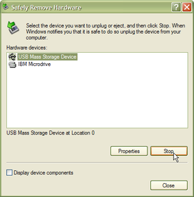
When you want to remove the USB disk, double-click on the Safely Remove Hardware button:
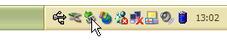
Choose the USB port attached to the disk, and click Stop.
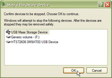
In the next window, check that the correct hardware is shown, and click OK to confirm.
You can now remove the hard disk from the computer and reinstall it in the DCM if required.
3.3 The DCM as a GCF data source
With a sufficiently fast serial link, you can instruct the DCM to send incoming data directly to a GCF-compatible client. For example, Güralp Systems' Scream! software allows you to display and record incoming data, as well as change the settings of attached digitizers. You can do this in addition to recording data on a local hard disk, or you can leave the hard disk uninstalled and operate the DCM entirely over the network link.
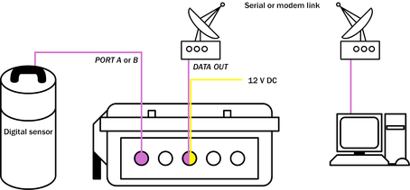
This example shows a module communicating with a local PC over a dedicated radio link. You could also use a simple serial cable to connect the DCM to the PC.
Connect the DCM to a digitizer or digital sensor.
Connect the DATA OUT port to a source of 12 V DC power.
Either use a computer connected to the NETWORK port to browse to the DCM's Web site, or log in to the Linux console over the serial link.
Find out the port number of the DCM's DATA OUT port. On the Web interface, the DATA OUT port is listed by name in the serial port table.
If you are using the Linux console, use the command gnblocks to display the port number.
On the Web interface, click the Port configuration link for the DATA OUT port, and set the serial.x.service option to gcf_out.
If using the Linux console, use the command gcfgdbset serial.x.service gcf_out (see Section 8.2, page 117.)
Note: Beyond this point you will not be able to use the serial link to access the Web configuration interface of the DCM. If you do want to be able to do this, you should configure the serial link for PPP (see “PPP”, page 100) and run a Scream! server on the DCM. You will need to assign the DCM its own IP address on your local network.
If you connected to the DCM by PPP, you will lose the network connection at this point, because the DCM is now using the serial link directly.
Open Scream!'s main window, and look under Local in the tree on the left for the serial port which is communicating with the DCM. If it is not shown, you may have to 'unfold' the tree to reveal it. The digitizer(s) attached to the DCM will appear underneath the entry for the serial port, and you can configure them from within Scream!. See Scream!'s documentation for more details.
If no digitizer is shown, it may be that your software is not configured correctly for the serial link. As supplied, the DCM uses a baud rate of 115200 on its CONSOLE port, with 8 data bits, no parity bits and 1 stop bit, and no flow control.
For more information on how to use Scream! to display and manage data streams, please see Scream!'s own documentation or the extensive on-line help.
Accessing the DCM command line through gcf_out
The gcf_out service provides a command-line terminal designed to be compatible with Güralp Systems' SAM serial storage device. To access this terminal from Scream!, right-click on the DCM's icon and select Terminal.... You will see a banner like
DCM DCM CRSM Command Mode
0 blocks in buffer | 16360 blocks free
The SAM commands you can use are described in the SAM Operator's Manual.
You can also log in to the DCM's Linux operating system through the terminal. Enter the command
GETTY
and press ENTER. You will be presented with the login: prompt.
If you are not using Scream!, and cannot make the unit enter SAM compatibility mode, you can interrupt the GCF data stream and drop straight to the login: prompt by connecting direct to the serial port and typing
forcegetty
It may take several attempts for this to succeed.
Another possible reason for setting the DATA OUT port's service to gcf_out is to allow several DCM units to work together and aggregate the inputs from an array of sensors.
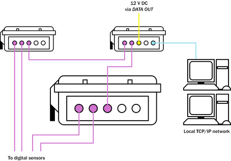
Here, DATA OUT ports with gcf_out as the service output data to the serial inputs of another DCM or AM module, which aggregates them all and sends them out over a network connection.
The DCM can handle multiple data sources with ease using the gcf_out service. In practice, however, it is almost always preferable to set up a local area network and use PPP over any serial links, so that GCF, Web and SSH traffic can share the same connection. Setting up a fully networked array is slightly more difficult than using gcf_in and gcf_out services, but provides much more flexibility.
3.4 The DCM as a network data hub
The most flexible way to operate the DCM is as a fully independent machine on your local area network. To do this:
Connect Güralp digitizers to PORT A and PORT B as necessary, using the serial data cable provided.
If you are using the DCM's USB capabilities, connect your external hardware or computer to the USB socket.
Note: In the USB standard, a device is either a host (a computer) or a client (a peripheral.) The DCM's USB port can act as either, depending on the options specified at manufacture. It cannot do both at the same time.
If your DCM is a host, you can attach additional USB peripherals such as hard disks to the USB socket. If it is a client, you can attach the USB socket to a computer, and it will appear as a network interface.
Connect a Güralp combined serial/power cable to the DATA OUT port. Make up a connector if necessary, and attach the power lines to a 12 V DC power supply.
Connect the 9-pin serial socket to a computer for configuration.
Connect an Ethernet cable to the NETWORK socket, and set up the network as described in Section 2.4, page 15.
You should now be able to connect to the DCM's Web setup interface by typing its IP address into any browser, e.g.
https://192.168.0.2/
By default you can use either http: or https: URLs to access the DCM's Web site. HTTPS is a secure variant of HTTP, which we recommend you use in preference to avoid passwords being sent over the network in clear text. Scream! and similar software applications should also be configured to use this IP address to communicate with the module. If the DCM is using a static IP address, you may assign it a name on your network (although you will still need to use the numeric IP address in Scream!.)
The DCM also runs a SSH (secure shell) server, which you can use to access its Linux command line over the network, just as if you had connected to it over a direct serial link. The standard Linux program ssh and the freeware Windows program putty are popular SSH clients.
If you do not wish to use the DCM's Web site, you can continue using the gcfgdbset command to set other configuration options by name. For the option names, you should refer to Chapter 4, “Configuration options” in the DCM manual, where each name is given in italics with a description of its action.
The command syntax to use is
gcfgdbset option-name new-value
The options will take effect immediately whenever possible. Some changes may take some time to complete, since services may need to be restarted. The gcfgdbset command performs only simple checks on the new value, so you should check the syntax of the option carefully.
You can configure attached digitizers from the DCM Web interface by clicking on the Configure – Digitizer link in the serial port table (see Section 2.6, page 22.)
You can also connect to the console of attached digitizers with the terminal command
minicom -n port-number
Alternatively, you can send individual commands to a digitizer with the command
gcli port-number command
In these commands, port-number is the port number and port-name the port device name to send the command to. To find out these, issue the command serialmap:
Library version: libserialmap Version 1.0.5 with LIBGCONFIGDB
3 serial ports
Port 0, Key 7000, name Data out port, device /dev/ttySA0, baud 115200
Port 1, Key 7001, name Port B, device /dev/ttySA1, baud 9600
Port 2, Key 7002, name Port A, device /dev/ttySA2, baud 19200
Each port will be listed, with its number (e.g. 0), name (e.g. Data out port), and device (e.g. /dev/ttySA0).
All data received by the DCM is periodically written from Flash memory to the on-board hard disk. The time period used can be configured from the Configuration – Disk page of the DCM's Web site.
You can list the files on the hard disk
over the Web, by selecting Tools – Disk files from the menu, or
from the command line with gfat32 ls
If you are using the Web page interface, each file appears as a link: click its name to download the file.
Alternatively, you can physically remove the internal hard disk, and attach it to any computer supporting either Firewire or the USB Mass Storage Protocol. It will appear on the computer as an extra hard drive. The DCM uses a journalling file system compatible with Windows' FAT32, so you cannot lose or corrupt data by removing the hard disk, even if the DCM is in the middle of writing to it.
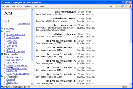
You can instruct the DCM to record data to Flash (and, later, its hard disk) in miniSEED format by browsing to the Configuration – Disk page and selecting yes for the disk.recordas.miniseed option.
The DCM allows you to record in several formats simultaneously, if you wish; you should make sure that you have the capacity to store, or the bandwidth to transfer, all the data the DCM will produce in each format you have enabled.
You can instruct the DCM to record data to Flash (and, later, its hard disk) in SAC format by setting disk.recordas.sac to yes.
The DCM can also compile full SEED volumes in real time. To enable this:
Edit the /etc/seed.cfg file. The DCM will only write SEED volumes for streams mentioned in this file. See “SEED recorder”, page 91, for more details.
Browse to the Configuration – Disk page, and set disk.recordas.seed to yes, or issue the command
gcfgdbset disk.recordas.seed yes
Click Save changes to save the configuration and start writing SEED volumes. One volume will be written for each stream every three hours. The DCM will always start a new volume if it is power cycled; the aborted file will still be a valid SEED volume.
You can use the DATA OUT port (or any of the DCM's serial ports) in several ways, depending on the service you have chosen to run on the port.
By default, the DATA OUT port runs the getty service, which allows you to connect to the DCM's console.
The mgetty and mgetty_raw services are similar, but can deal with connections made through modems.
The gcf_out service causes the DCM to combine the incoming GCF streams and send them on transparently, as for a Güralp SAM or CRM.
The gcf_in service turns the port into an extra digital data input port. The DCM's PORT A and PORT B run the gcf_in service.
To change the service running on a port, click the Configure – Port link in the serial port table, and set the serial.x.service option to the required value. Alternatively, issue the command
gcfgdbset serial.x.service service
In a straightforward vault installation, we recommend that you leave the DATA OUT port running the getty service for emergency console access, and instruct the DCM to act as a server for incoming data on your network. This can be done from the Data transfer – Scream server page on the Web site:
Enable the Scream! server on the DCM by setting datatransfer.scream.server to on and datatransfer.scream.server.allowserialaccess to yes. Make a note of the port number datatransfer.scream.server.port, or change it to another. Click Save settings.
Start up Scream!, and select Windows – Network Control... from the main menu. Switch to the My Client tab.
If it is not already selected, check Receive Data to start Scream! listening.
Right-click anywhere in the Servers list box, and select Add UDP Server.... Enter the IP address and port number of the DCM, separated by a colon : (e.g. 192.168.0.2:12345)
Test communications by right-clicking on the newly-added server, and selecting GCFPING. A message appears in the Control pane logging the ping being sent. If communication is good, and the server is enabled for client requests, you will receive a GCFACKN message from the server which will also appear in the Control pane.
Request data by right-clicking on the server and selecting GCFSEND:L (or GCFSEND:B) from the pop-up menu.(L is used for little-endian and B for big-endian byte order, and are distinguished for compatibility.) Streams should soon begin to appear in Scream!'s main window.
To stop the link, right-click as before and select GCFSTOP from the pop-up menu. If you do not GCFSTOP, the server will continue to transmit to a client that is no longer listening. You should ensure that the server replies with a GCFACKN message If an acknowledgement does not appear in the Control pane, repeat the GCFSTOP command.
The DCM can be configured to transmit incoming data to a specified client using the CD1.0 or CD1.1 protocols. If you intend to send CD1.0 or CD1.1 data to a National Data Centre (NDC), the installation will need to be assigned a unique code by the International Seismic Centre or with the US's National Earthquake Information Center.
To enable CD1.0 or CD1.1 transmitters, browse to the Data transfer – CD1 (CD1.0) Sender or Data transfer – CD1.1 Sender page. Fill in the required data fields and click Save settings.
Using an Authentication Module (AM), you can cryptographically sign all outgoing CD1.0 or CD1.1 subframes as they pass through. This is particularly powerful where the module is physically part of the sensor casing, as it allows you to generate authenticated data at source, even within a borehole.
AutoDRM (Automatic Data Request Manager) is an optional service which allows you to request data over e-mail. In response to a request, the AutoDRM can either send an e-mail in return, or establish an FTP connection to you.
Not all DCMs have these packages installed. If you are unsure, or wish to upgrade, contact Güralp Systems.
In order for the AutoDRM system to work, the module must be able to send and receive e-mail messages. To set the system up, you will need to fill in the details of your network's SMTP server under Configuration – Outgoing mail, and of your POP or IMAP server under Configuration – Incoming mail. Remember to click Save changes after you have filled in each screen.
Switch to the Data transfer – AutoDRM page, and enable datatransfer.autodrm. Click Save changes on this page to start the service.
To test the AutoDRM system, send the following e-mail to the DCM:
From: your@e-mail.address
To: autodrm@your.DCM
BEGIN GSE2.0
MSG_TYPE request
MSG_ID unique-identifier
HELP
EMAIL your@e-mail.address
STOP
where your@e-mail.address is the e-mail address to send the return message and unique-identifier is a string which you can use to identify your request. autodrm@your.DCM should be replaced with an e-mail address which will be delivered to the autodrm mailbox on the DCM.
The DCM should send a mail back to you containing help on the commands you can give the AutoDRM system.
3.5 Troubleshooting DCM installations
I cannot connect to the DCM's DATA OUT port using a terminal program.
Press ENTER a few times to initiate communication.
If the DATA OUT port gives a login prompt, you should log in with your username and password. If you have not been given a different username and password, try logging in as root with the password rootme. You should change this password as soon as you can with the command passwd
If the DATA OUT port gives an ok prompt, the DCM is running the gcf_out service on that port and has provided you with a FORTH compatibility interface. Type
GETTY
and press ENTER to gain access to the login prompt.
If the DATA OUT port does not respond when you press ENTER, or produces garbage, check that your terminal program is using the same baud rate as the DCM. By default, the DCM uses a baud rate of 115200, with 8 data bits, no parity bit and 1 stop bit, and no flow control.
If the DATA OUT port produces a large quantity of characters, it may be sending GCF data. Try typing
forcegetty
repeatedly. If the DCM is running the gcf_out service on this port, it will stop transmitting and give you access to the login prompt.
If the DATA OUT port is not responding at all, check the power supply to the DCM.
I cannot see the DCM's Web site over HTTP or HTTPS.
There is a problem with the network setup. Connect to the DCM's DATA OUT port using a terminal program and change the network settings to suit your network. In particular:
If the DCM has a static IP address, use ifconfig to verify that the DCM is using the correct IP address. If it is not, change it with
gcfgdbset net.eth.0 static
gcfgdbset net.eth.0.netmask 255.255.255.0
gcfgdbset net.eth.0.address 192.168.0.2
(replacing 192.168.0.2 with the IP address you want the DCM to use.)
If the DCM is using DHCP, use ifconfig to verify that the DCM is using the IP address you expected. If it is not, change the settings of your DHCP server or connect to the correct IP address for the DCM
Check that your local PC can route to the DCM's IP address. For example, if you are using a cross-over Ethernet cable, the two hosts must share a subnet.
Check that the DCM's HTTP(S) server is enabled by issuing one of
gcfgdbset net.remoteaccess.allow.http yes
gcfgdbset net.remoteaccess.allow.https yes
as necessary.
I cannot connect to the DCM's Scream! server.
Make sure you are using UDP to connect to the DCM. Scream! servers between computers (including the DCM) always use UDP. The Add TCP server... option in Scream! is intended for hardware serial-to-IP converters only.
I cannot GCFPING the DCM's Scream! server.
Check the Receive UDP data checkbox in Scream!'s Network Control window.
Open the DCM's Web site, and check that the option datatransfer.scream.server is set to on, and that datatransfer.scream.server.port is the port you expected.
I can GCFPING the DCM's Scream! server, but no data appears.
Check the DCM is receiving data by selecting Actions → Data Viewer on its Web site. This is a Java applet which provides some of the functionality of Scream!, allowing you to check that data is being received correctly.
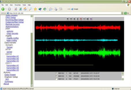
The streams being received at the DCM are listed in the bottom section of the applet. Click on a checkbox to add that stream to the main viewer window.
If you do not want to use the DCM's Web site, you can find out the number of GCF blocks the DCM has received with the command gnblocks. Each serial port will be listed, with its name, number, key number and device name (as for serialmap) but including the number of blocks received on that port:
Key 0x007005: Blocks 3287 (Port 5, name Port A (COM6),
device /dev/ttyS2, baud 9600)
The DCM is not receiving any data streams.
Check the connection between the digitizer and the DCM by trying to log in to the digitizer's console using any of the methods described in Section 3.4 (page 33.) Press ENTER a few times to initiate communication.
If the digitizer gives an ok prompt when you press ENTER, check that you have configured the digitizer to output real time data streams. Streams will not appear until a whole GCF block (1024 bytes) is ready for transmission, so a 5 sps stream may not appear until the digitizer has been working for 4 minutes. In addition, you can configure a digitizer to output only triggered streams, in which case it will not appear until a trigger occurs. (There is an exception to this: if you have put the digitizer in the FILING or DUAL filing mode, it will send heartbeat messages to Scream! clients every so often. The DCM will not show these messages in the Data Viewer.)
If the digitizer does not respond when you press ENTER, or produces garbage, check that the DCM is using the same baud rate as the digitizer. By default, digitizers use a baud rate of 9600, with 8 data bits, no parity bit and 1 stop bit, and no flow control. To change the DCM's settings, exit the terminal program, and either
access the DCM Web site, click on the Configure – Port link in the serial port table, and change the settings, or
issue configuration commands such as
serial.5.service gcf_in
serial.5.baudrate 9600
serial.5.handshaking none
If the digitizer is not responding at all, check the power supply to the digitizer and the cable between it and the DCM.
To obtain the port number (here 5) corresponding to a named port, use the command gnblocks.
The DCM is receiving streams, but they do not contain any data.
If the data you see is zero:
Increase the Y axis scale using the
 icon in Scream!'s Waveview window or the corresponding icon in the DCM's Data Viewer.
Check the mass position outputs to see if the masses are locked. A properly unlocked and centred mass should show a mass position within 1000 counts of zero; a locked mass will give a value greater than 32,000 (or less than −32,000) counts. If your sensor has remote mass locking, you can unlock the masses by navigating to Actions → Digitizer setup and clicking Unlock sensor.
Locking or unlocking the sensor mass typically takes several minutes to complete.
Check the connection between the sensor and digitizer and try again.
If you cannot see the data in the stream, remove any constant offsets by clicking on the Zero streams icon  in Scream!'s Waveview window or the DCM's Data Viewer.
The DCM receives streams, but gaps appear in the data some minutes after boot-up.
Check that the baud rate between the digitizer and the DCM is sufficient for all the data streams you want to transmit. If it is not, the digitizer's output buffer will gradually fill up until no more data can be stored. Increase the baud rate of the digitizer through the DCM (or using Scream!), then set the baud rate of the DCM's input port to the same value.
If you are using triggered output streams, be especially careful to allow a high enough baud rate to transmit data from all possible output streams simultaneously, or you will observe gaps when an event triggers the digitizer.
The DCM receives streams, but 2-minute gaps appear in the data at 4-hour intervals.
After a reboot, the DCM takes around 2 minutes to begin transmitting. The DCM runs a guardian process which monitors the health of the system. In some circumstances guardian will need to reboot the DCM to attempt to resolve a problem. If the reboot does not help, the DCM will soon find itself in the same position, and guardian will reboot it again.
You can check the time since the last reboot with the command uptime, which will respond with a line like
14:30:32 up 34 min, load average: 1.24, 1.32, 1.10
In this example, the DCM last rebooted 34 minutes ago.
The most common circumstance where guardian will reboot a DCM is when the operator has instructed it to record data, but it cannot do so. This may be because
the Flash memory is full, and all connected USB disks are also full,
the Flash memory is full, and no USB disk is present;
the Flash memory is full, and a USB disk is inaccessible for some other reason (e.g. it is unformatted, incorrectly partitioned, or faulty); or
the Flash memory is being filled up faster than the DCM can empty it. This may happen if the individual files are longer than 25% of the total Flash memory in each of the two memory banks (e.g. 16 Mb, for DCMs with 128 Mb of storage.) If you encounter this problem, try making the watch files shorter by changing the value of disk.recordinterval (see Section 6.3, page 86.)
3.6 CMG-AM Authentication Modules
The CMG-AM is a variant of the CMG-DCM which includes strong cryptographic capabilities, including an on-boad Spyrus crypto-token.
This token can be used to sign all outgoing data at source. The signature matches the data as produced, so if anyone alters the data, the signature will no longer be correct.
Before your DCM can start sending authenticated data, it must
generate a cryptographic key pair;
request a certificate from a trusted Certificate Authority, and be assigned one;
run a data server or transmitter using a protocol designed with provision for authenticated seismic data (e.g. CD1.0 and 1.1);
using the certificate and key, begin authenticating the data using the method specified in the protocol.
These steps can be executed remotely, but must be carried out separately for each installation.
Where a Spyrus crypto-token is installed, the program spyrus should be used to set it up.
From a computer on the local network, use a suitable program to open a ssh session with the AM. For example, from a Linux computer:
ssh 10.82.0.129
where 10.82.0.129 should be replaced with the IP address of the AM on your network.
Log in using the username and password you use to access the AM's Web interface. (If you do not use a username and password to access the AM's Web interface, you should obtain one from your network administrator.)
Initialise the Spyrus card with the command
spyrus zeroize
followed by
spyrus start
You should see information messages coming from the Spyrus card, as follows:
Initial state 8(Zeroized)
info::state: Zeroized
info::logging into zeroized card
info::state: Uninitialized
info::logging into unitialized card
info::loading initialization values
info::state: Initialized
info::changing SSO password
info::state: SSO Initialized
info::logging into the card as SSO
info::loading the trusted certificate
info::state: LAW Initialized
info::logging into the card as SSO
info::setting the user's password
info::state: User Initialized
info::logging into the card as User
info::state: Standby
info::Final state 6(Standby)
If the AM reports an error, the spyrus package is not installed or cannot function. In this case, you should use openssl to generate keys in software as described below.
Now log in using
spyrus login
Create a text file containing information about the station, sensor, etc., in the following format:
organizationName:your-organization
organizationalUnitName:station-name
organizationalUnitName:operator-name
localityName:HPAXX
commonName:HPA0-02
commonName:HPA0-01
This will be used to request the certificate. You should replace the information after the colons with the correct data for the specific pit installation (available from the NDC or the station administrator.) Check that the field names (before the colons) are correctly capitalized, and do not leave spaces around the colons.
You can have several organizationalUnitName and commonName records, in which case the information is entered into the database from bottom to top, so that the most recent entries appear first in the file.
(To create a text file in Linux, either use a command like cat > filename and enter the data directly, ending with CTRL-D, or use the text editor vi. Using vi will allow you to edit the file should you make a mistake in entering the data. For more information, see the Linux manual page for vi. Alternatively, you can create text files on the local computer and transfer them to the AM module using scp or a similar secure transfer program.)
Change into the CD1.1 transmitter's configuration directory using
cd /etc/libcd11
The following steps create a key pair and certificate request within the token, which need to be placed in this directory for the CD1.1 transmitter to be able to sign outgoing data.
Issue the command
spyrus newreq -s filename -i 1 -r slot01.req -p slot01.pub -x
where filename is the name of the file you created in step 5. This will generate a certificate request in the file slot01.req and a public key in the file slot01.pub. The private key is kept within the token itself, and cannot be extracted from it. Any attempt to compromise the token will cause it to shut down and become unusable.
The file slot01.req is a certificate request for the key pair generated. You should send this file by e-mail to the Certification Authority, so that they can generate a valid certificate from it.
When you receive the certificate, install it in the /etc/libcd11 directory as slot01.crt. Also create the key ID file slot01.kid. (The key ID file is simply a text file containing the key ID as a single decimal number. You can use any key ID number as long as it is unique for each key. It is used in the key bucket file, described below.)
Now load the certificate into the token using the command
spyrus loadcert -c slot01.crt
The token will check that the certificate matches its own key pair, and should respond with
info::No index specified searching for matching key
info::Key in slot 1 matches certificate
If it reports that the key does not match the certificate, you may have attempted to load a certificate valid for the wrong token. Check the certificates you have received, and try again. Otherwise, you may have to generate a new certificate request and re-send to the Certification Authority.
If you issue spyrus loadcert without specifying a slot number, as above, any running CD1.1 transmitters will be interrupted, and you will need to restart them.
The token is now ready to start signing outgoing CD1.1 subframes. However, you will need to configure the format of these subframes by editing the /etc/cd11sf.cfg configuration file. You can do this either directly, or using the Web configuration interface (see Chapter 6, page 80.)
Any further key changes can be handled automatically over AutoDRM. However, occasionally you may want to supersede an existing key, or create a new key for a separate stream.
Keys are handled by a system of key buckets. Each key bucket consists of a list of keys and activation times. Once the activation time for a new key passes, the previous key is superseded, and subsequent subframes are signed by the new key. You can have a different key bucket active for each stream, or even several key buckets for the same stream.
Key buckets are stored in the files 0.bkt, 1.bkt, etc., within the /etc/keybuckets directory. Each line in a key bucket file has the format
key-id:days-since-epoch:seconds-since-day-start
where days-since-epoch is the number of days elapsed since November 17, 1989. The CD1.1 transmitter scans this file in order, and stops when it finds a key with an activation time in the past (relative to the time-stamp of the data being transmitted.) Thus, to supersede an existing key, you must place the new entry before the old one in the file, so that the CD1.1 transmitter will not continue signing subframes with the old key.
To make the CD1.1 transmitter sign all subframes with a new key, even when backfilling, you should add the line
key-id:0:0
to the beginning of the file.
Restart the CD1.1 transmitter with the command killall -HUP cd11sf. (Using the -HUP option makes the command send a hangup signal to the CD1.1 transmitter rather than killing it outright.)
Some AM units are not supplied with hardware crypto-tokens. These units can still perform authentication using the openssl package. To set up an AM using openssl:
Change into the CD1.1 transmitter's configuration directory using
cd /etc/libcd11
Generate the DSA parameters file with
openssl dsaparam -out slot01.prm key-length
where key-length is the size of the key you wish to be generated (normally 1024.)
Generate the public and private keys with
openssl dsaparam -in slot01.prm -out slot01.key -genkey
Create a configuration file in the format
[req]
default_bits = key-length
distinguished_name = req_dn
[req_dn]
organizationName = Enter organization name (eg, company)
organizationName_value = organization-name
0.organizationalUnitName = Enter organizational unit name (eg, section)
0.organizationalUnitName_value = organizational-unit-name
1.organizationalUnitName = Enter organizational unit name (eg, section)
1.organizationalUnitName_value = organizational-unit-name
localityName = Enter your station name
localityName_value = station-name
commonName = Enter your site name
commonName_value = site-name
You should only replace the words highlighted like this in the above file. The lines ending Enter your site name, etc., are used by openssl to generate prompt strings and need not be changed. If you need to enter two separate values for the same key (as organizationalUnitName above) you should prefix the pairs with 0., 1., etc., as shown.
Generate a certificate request with
openssl req -new -key slot01.key -days validity-period -config config-file -out slot01.req
where validity-period is the number of days' validity you want for the request, and config-file is the configuration file you created in the previous step.
The file slot01.req is a certificate request for the key pair generated. You should send this file by e-mail to the Certification Authority, so that they can generate a valid certificate from it.
When you receive the certificate, install it in the /etc/libcd11 directory as slot01.crt. Also create the key ID file slot01.kid. (The key ID file is simply a text file containing the key ID as a single decimal number. You can use any key ID number as long as it is unique for each key. It is used in the key bucket file, described below.)
The AM is now ready to start signing outgoing CD1.1 subframes. However, you will need to configure the format of these subframes by editing the /etc/cd11sf.cfg configuration file. If you intend to use CNSN authentication, you should also edit the /etc/cnsn.cfg configuration file. The AM's configuration files can be edited using its Web page interface or with an editor.
Any further key changes can be handled automatically over AutoDRM. However, occasionally you may want to supersede an existing key, or create a new key for a separate stream.
Keys are handled by a system of key buckets. Each key bucket consists of a list of keys and activation times. Once the activation time for a new key passes, the previous key is superseded, and subsequent subframes are signed by the new key. You can have a different key bucket active for each stream, or even several key buckets for the same stream.
Key buckets are stored in the files 0.bkt, 1.bkt, etc., within the /etc/keybuckets directory. Each line in a key bucket file has the format
key-id:days-since-epoch:seconds-since-day-start
where days-since-epoch is the number of days elapsed since November 17, 1989. The CD1.1 transmitter scans this file in order, and stops when it finds a key with an activation time in the past (relative to the time-stamp of the data being transmitted.) Thus, to supersede an existing key, you must place the new entry before the old one in the file, so that the CD1.1 transmitter will not continue signing subframes with the old key.
To make the CD1.1 transmitter sign all subframes with a new key, even when backfilling, you should add the line
key-id:0:0
to the beginning of the file.
If you are running it, restart the CD1.1 transmitter with the command killall -HUP cd11sf. (Using the -HUP option makes the command send a hangup signal to the CD1.1 transmitter rather than killing it outright.)
If you are running it, restart the CNSN transmitter with the command killall -HUP cnsnauth