Chapter 5. Data transfer
You can retrieve data from the DCM using a variety of standard seismic network protocols and formats, including Güralp Systems' own Scream! software. The options beneath Data transfer are used to configure these network services.
For data transfer options which use the serial ports of the DCM (e.g. DSS summary mode, etc.) you should use the Configuration – Serial ports pages to set the serial.x.service option instead (see Section 6.2, page 82.)
5.1 Scream! server
Scream! is a Microsoft Windows software package designed to configure and retrieve data from Güralp digitizers. The options on this page allow you to control how the DCM responds to requests from Scream!. Depending on your requirements, the DCM can act either as an instrument in itself, or pass through requests directly to connected equipment.
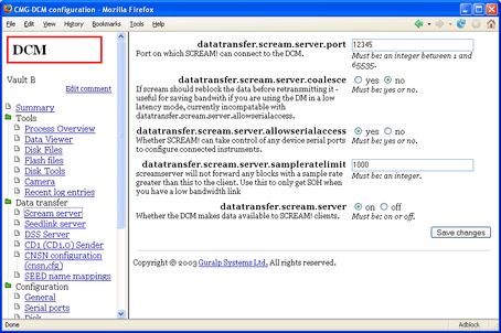
datatransfer.scream.server : Select on to allow Scream! to connect to the module over a TCP/IP connection and receive data as if it were a connected instrument. The connection can be established over an Ethernet, wireless, or PPP link. If you do not want to transfer data directly to Scream! clients, select off.
datatransfer.scream.server.allowserialaccess : The Scream! software allows you to configure digitizers connected to it by serial links. Select yes if you want to be able to use Scream! to configure digitizers attached to the DCM's serial ports. The software is able to differentiate between several instruments connected to the DCM, so enabling this option will allow you to configure all attached digitizers from within Scream!.
datatransfer.scream.server.port : The network port number which Scream! clients should use to connect to the DCM. You can use any port which neither the PC nor the DCM is using for other purposes. See your Scream! configuration for the current port setting; the default is 1567.
datatransfer.scream.server.udp_push : A list of clients to send UDP data, separated by commas.
Normally, clients connect to the DCM's Scream! server by sending a special UDP packet called GCFSEND, or by making a TCP connection to the server. In both of these cases the client is “pulling” the data from the DCM. Any client can connect to the DCM, but the client needs to know the DCM's IP address.
In some cases, e.g. when the DCM has a dynamic IP address, you may want the DCM to “push” UDP data to clients. To do this, you should add the clients to this list.
Each entry in the list is either the IP address or the hostname of the client. The DCM will send data to port 1567 by default. If you want to use a different port, use IP-address:port or hostname:port.
For example, the value
192.168.2.2, 82.68.239.4:8888, screamclient.remote.net
would cause the DCM to push data to port 1567 at 192.168.2.2 and screamclient.remote.net, and to port 888 at 82.68.239.4.
If UDP “push” is active, other clients can still connect to the DCM and “pull” data from it as normal.
datatransfer.scream.server.sampleratelimit : The fastest sample rate allowed for transmission over this connection. Using this option, you can prevent high-rate streams from being transmitted to Scream!, whilst allowing them to be transmitted by other means (e.g. CD1.1, etc.)
Setting this option to zero will filter out all data streams but preserve status channels, allowing you to use Scream! to monitor the status of your instrumentation whilst minimizing the bandwidth used.
datatransfer.scream.server.coalesce : Some digitizers are configured to produce GCF blocks at higher than normal rates. This may be done, for example, to reduce the latency in data transmission. Blocks produced this way may not all be full, so space will be wasted in the recording medium.
Selecting this option makes the DCM build full GCF blocks from the data it receives (a process known as re-blocking) before transmitting them.
If you enable datatransfer.scream.server.coalesce, you will not be able to connect to the terminal of any connected digitizers using the Scream! server (i.e. the DCM will behave as if datatransfer.scream.server.allowserialaccess was no.)
You can still configure the digitizers using the Web page (Section 7, page 105) or using command line tools like minicom and gcli (see Section 8.2, page 117).
5.2 SeedLink
SeedLink is another member of the SEED / MiniSEED family of formats, designed for transferring seismic data over a network. The DCM's slserver package provides a SeedLink server.
SeedLink expects streams to be named using station, channel, and network codes according to the FSDN SEED naming convention. Before using the SeedLink server, you will need to define these codes for every stream you expect to receive. This is done on the Seed name mappings page (see Section 5.7, page 75.)
The following configuration options are available:
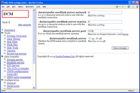
datatransfer.seedlink.server.network : The default 1- or 2-character SEED network code to use for this station.
datatransfer.seedlink.server.station : The default SEED station code to use, up to 5 characters long.
datatransfer.seedlink.server : Select on to enable the server, off to disable it.
datatransfer.seedlink.server.port : The network port on which to listen for incoming connections.
Before you can start the SeedLink server, you will need to tell it which streams to output, and what SEED codes to use for each one. This is done on the Seed name mappings page (see Section 5.7, page 75.)
You should make sure that each stream uses the same SEED network and station codes as you have configured for the server on this page.
When you have finished editing these options, click Save changes to commit them.
The SeedLink server will not immediately use the new options, because clients may still be connected. You will need to restart the SeedLink server at a convenient time. Clients will have to reconnect to the new instance of slserver before they can continue receiving data.
To restart the SeedLink server, browse to the Tools – Process Overview page and find the entry for the slserver process. Click the Restart link in this entry.
5.3 DSS
DSS (Data Subscription Service) is a packet format which enables data and statistics to be requested from a seismic installation. A DSS server is designed to handle many concurrent requests from clients with varying levels of privilege, and may prioritize requests according to their origin and urgency.
Güralp Systems' data modules include a package, libdss, which is designed to communicate with installations using DSS as either a server or a client. A daemon utility, dssserver, is also available which receives requests on a network port and replies to them.
dssserver initially listens on a network port for DSS_REG registration packets from clients. Any incoming connnections other than DSS_REG are refused with a DSS_REF packet. Receiving a valid DSS_REG packet, dssserver sends a DSS_ACK packet and adds the client to an internal client list, identified by its source IP address and port number.
Once a client is registered, dssserver will accept other DSS command packets from it.
dssserver fulfils requests by following this procedure:
Receiving a valid DSS_REQ packet, dssserver will send a DSS_ACK packet immediately and add the request to an internal subscription list.
Receiving a valid DSS_DEL packet, dssserver will find the corresponding request in the subscription list, remove it, and reply with a DSS_ACK packet. If the relevant data has already been transmitted, dssserver will still send the DSS_ACK packet to notify the client that the request has been dealt with.
dssserver keeps a record of the subscriptions for each client so that it can respond to DSS_LRQ packets. When a subscription is fulfilled, it is removed from the relevant list.
Other valid DSS commands are dealt with according to the standard.
When data arrives from connected digitizers, dssserver examines the current queue of data requests, and generates the required data or averages separately for each client, in accordance with these requests. This data is placed in a train, which is a data structure whose length is determined by the reporting interval. Every train includes data from the vertical, N/S, and E/W component of a particular instrument.
As soon as the received or generated data fills the buffer, it is ready for dispatch. dssserver forms the data into a DSS_DAT message and sends it to the client, identifying it with the relevant Data Identification Word.
Every 10 minutes or thereabouts, dssserver checks the client list for any clients which have not reported to it in the past 10 minutes, and purges the inactive clients from the list.
dssserver does not implement advanced prioritization or queuing schemes. All clients connect with the same password.
DSS expects streams to be named using station, channel, and network codes according to the FSDN SEED naming convention. Before using the SeedLink server, you will need to tell it which streams to output, and what SEED codes to use for each one. This is done on the Seed name mappings page (see Section 5.7, page 75.)
The options on the Data transfer – DSS page are:
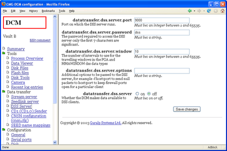
datatransfer.dss.server : Set this to on to run the server; off to disable it.
datatransfer.dss.server.port : The port number on which to listen for incoming DSS packets. The default is 9000.
datatransfer.dss.server.password : The password all clients should use when registering with dssserver.
datatransfer.dss.server.window : The number of DSS intervals to use for travelling windows (used in the PGA and MMAWINDOW data types). The default is 10.
datatransfer.dss.server.options : Any additional options to send to the DSS server process (for advanced usage.)
Remember to click Save changes before you browse away from the page, if you want to keep the changes you have made.
The DSS server will not immediately use the new options, because clients may still be connected. You will need to restart the DSS server at a convenient time. Clients will have to reconnect to the new instance of dssserver before they can continue receiving data.
To restart the DSS server, browse to the Tools – Process Overview page and find the entry for the dsserver process. Click the Restart link in this entry.
5.4 CD1 (CD1.0) Sender
Continuous Data Format, CD1.0, is a standard method for sending seismic data over a TCP/IP network. The DCM module can send data in CD1.0 format to a specific CD1.0-compatible device or NDC.
Some installations of the DCM have multiple CD1.0 senders. In this case, there will be several sender pages, all with the same options.
datatransfer.cd1.sender : Select on to activate the CD1.0 sender. If you do not want the DCM to transmit CD1.0 data, select off and ignore the remaining settings.
datatransfer.cd1.sender.sitename : The CD1.0 site name for the DCM.
datatransfer.cd1.sender.receiver : The IP address or hostname of the remote CD1.0 device.
datatransfer.cd1.sender.port : The network port number to which the DCM will send CD1.0 data.
datatransfer.cd1.sender.compression : Select on to enable Canadian compression in the outgoing data stream.
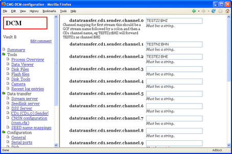
datatransfer.cd1.sender.channel.x : The DCM needs to know the CD1.0 channel name for each of the streams you want to transmit. When data comes in on a stream that the DCM recognizes, it will send it on with this new name. You can configure up to 12 channels to be transmitted by one CD1.0 sender.
Channel names are normally chosen to conform to the FSDN SEED naming convention, but you can use different names if you wish. The CD1.0 sender does not use the current Seed name mappings.
5.5 CD1.1
The CD1.1 format is an evolution of CD1.0 used by many NDCs, using different settings from CD1.0. The DCM has a separate transmitter for this format.
datatransfer.cd1_1.tx : Select on to instruct the DCM to provide data in this format. If you do not want the DCM to transmit CD1.1 data, select off and ignore the remaining settings.
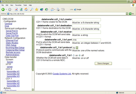
datatransfer.cd1_1.creator : An 8-character string specifying the source of the data (i.e. the instrument or array to which the DCM is attached.)
datatransfer.cd1_1.destination : An 8-character string specifying the intended destination of the data.
datatransfer.cd1_1.port : The network port number to which the DCM will send CD1.1 data.
datatransfer.cd1_1.protocol : The network protocol the DCM should use to send CD1.1 data—currently only tcp is supported.
datatransfer.cd1_1.receiver : The IP address or hostname of the remote CD1.1 device.
For the CD1.1 sender to be able to build frames, it needs to have access to detailed status information from the digitizer. This is provided in a special digitizer stream ending CD. This stream is not output by default: to make the DM24 output a CD stream, connect to its console and issue the command
+MONITOR
This can be done from the DCM command line (see Section 8.2, page 117) with the command
gcli n '+monitor'
where n is the number of the serial port attached to the digitizer.
CD1.1 data is organised into subframes, which have some flexibility in their format. A configuration file, /etc/cd11sf.cfg, is provided allowing you to specify the exact format to be used in outgoing CD1.1 subframes. Clicking CD1.1 subframe configuration brings up a page in the work area which enables you to edit the file and its attributes directly.
The Web interface does not check that the content of the files will be understood. You should ensure that the file is valid before committing any changes.
Each line in /etc/cd11sf.cfg describes a single CD1.1 stream in the format
data-stream:status-stream:location:site:instrument:channel:prefix:key-bucket
where the fields, separated by colons, are:
data-stream : the digitizer's data stream ID;
status-stream : the digitizer's status stream ID;
location : the CD1.1 location code for the array;
site : the CD1.1 site code for the instrument;
channel : the CD1.1 channel name;
prefix : a prefix for the location to store the files in the file tree of the DCM.
key-bucket : the key-bucket code, which tells the DCM which key to use for that particular stream.
The cryptographic hardware required to produce authenticated CD1.1 streams is installed only in Authentication Modules (AMs). If you do not have this hardware, you can transmit unauthenticated CD1.1 data by using a key-bucket code of -1.
prefix : A prefix used to determine where to place generated CD1.1 subframes. For example, a prefix of /data/HPA1. will produce files in the /data/ directory beginning with HPA1. and followed by a unique timestamp. Several streams may produce files using the same prefix; indeed, this is recommended.
Blank lines, and any lines beginning with #, are ignored.
When you have finished editing the file, clicking Save changes will write the changes to disk. The changes will not take effect, however, until the CD1.1 service is restarted. You can restart all running CD1.1 services by clicking Restart CD1.1.
5.6 CNSN configuration (cnsn.cfg)
This option is only functional on Authentication Modules (AMs) with an on-board cryptographic token.
In this system, a signature is generated from incoming data, which is transmitted together with the compressed data. At the receiving end, the signature is regenerated and compared with the one sent to establish authenticity.
To use the CNSN system, you will need to set exactly one serial.x.service option to cnsn_in, and one to cnsn_out (see Section 6.2, page 82.) You will also need to edit the file /etc/cnsn.cfg, which defines the streams.
Each line in /etc/cnsn.cfg describes a single CNSN stream in the format
method:key-id:high-byte:low-byte:site:channel[:location]
where the fields, separated by colons, are:
method : The compression/signature method, one of canadian_compression_after_signing, canadian_compression_before_signing, canadian_as, canadian_bs, steim_as, steim_bs, or none
key-id : The ID of the key to use for the stream, as used in /etc/libcd11/slotxx.kid and /etc/cd11sf.cfg
high-byte and low-byte : The two CNSN stream identifier bytes, expressed as decimal numbers.
site : the site code.
channel : the channel code.
location : optionally, the location code.
Blank lines, and any lines beginning with #, are ignored. When you have finished, click Save changes.
The Web interface does not check that the content of the file will be understood. You should ensure that the file is valid before committing any changes.
5.7 SEED name mappings
Several seismic network formats use the FSDN SEED naming convention to identify channels.
Before you can connect Güralp Systems instruments to a network using this convention, you will need to define mappings between the raw stream names from the digitizer (e.g. DEMOZ2) and the FSDN SEED names for the same streams (e.g. GB:GSL:BHZ).
This mapping is defined in an XML file stored at /etc/seedmap2.xml. Clicking on Data transfer – SEED name mappings opens a page allowing you to view and edit the mapping.
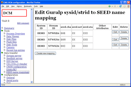
The table on this page shows all the streams which have SEED name mappings. If a mapping is defined for a stream, services which use SEED names will automatically transmit that stream.
the System ID and Stream ID for each stream which has a mapping;
the 3-character SEED channel name in use for the stream;
the 1- or 2-character SEED network name in use for the stream;
the 3-character SEED station name in use for the stream;
any other attributes you have defined for the stream and
buttons allowing you to Edit and Delete the entry.
Clicking Edit brings up a page where you can edit these attributes.
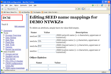
Enter values into the seed.net, seed.sta and seed.cha boxes to change the mapping. If one of these values is missing, services which use the SEED name mappings will ignore the stream.
If you are using SEED location codes, enter a value into the seed.loc box to set the location code for this stream. Location codes should be used in cases where several instruments with the same conventional SEED name are located at the same station.
Finally, you must enable output of this stream using each of the protocols you are using. This is done by adding an entry to the Other Entries section with the name protocol.enabled and the value true.
For example, to make a stream available over SeedLink, enter seedlink.enabled under Name, and true under Value.
To stop transmitting a stream, change the Value of this entry to false, or remove it.
You can add other information about your instruments into this file. For example, you might want to program the DCM with response and sensitivity parameters for your instrument.
To add additional information, enter the name of a quantity (e.g. sensitivity) in one of the Name boxes, and its value (e.g. 3000) in the Value box beside it.
This information is not currently used by any DCM services.
Click Save changes to commit your changes, or Cancel to return to the table without changing anything.
The SEED name mappings are used by MiniSEED, SeedLink and DSS. SEED names are also used by the full SEED recorder, but this requires additional data. You should supply this data in SEED's own configuration file /etc/seed.cfg (see above.)
CD1.0 and CD1.1 protocols use channel names which are very similar to SEED names. However, there may be instances where the CD1.0 and CD1.1 names need to differ from the FSDN SEED name, or where you do not want to transmit streams automatically. Because of this, the CD1.0 and CD1.1 services do not look for mappings in this file.
5.8 AutoDRM
AutoDRM is an automated system for handling requests for seismic data over e-mail, and for fulfilling those requests either by returning e-mails or by establishing an FTP connnection. In order for the AutoDRM system to work, the module must be able to send and receive e-mail messages: this can be configured using the Incoming and Outgoing mail setup configuration pages. See “Incoming mail setup”, page 97, for more details.
The DCM's AutoDRM capabilities are compatible with the GSE2.0 and 2.1 message standards developed for GSE-EISMS and GSETT-3.
datatransfer.autodrm : Select on to enable the DCM to handle AutoDRM requests.
datatransfer.autodrm.maxpoolsize : The maximum pool size to use whilst processing AutoDRM requests, in megabytes.
5.9 HTTP server
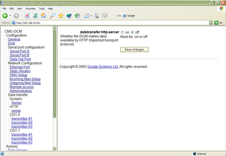
In addition to configuring the DCM and instruments attached to it, you can also instruct the on-board Web server to provide data to network clients.
datatransfer.http.server : Select on if you wish to be able to retrieve data from the DCM over the Web (i.e. HTTP). Once the HTTP server is enabled, you can browse through the DCM's hard disk using the URL http://mydcm/cgi-bin/explorefs?path=/.
You will need to use your username and password to access this service.