Chapter 4. Tools
The menu bar of the DCM's Web site is divided into four sections.
At the top is a banner identifying the DCM, with an optional comment. There is also a link to the Summary page, which is the one you see when you first open the DCM's Web site.
The next section, Tools, contains links which perform various actions on the DCM. This includes viewing data, transferring files from Flash memory and the on-board USB disk, and troubleshooting.
Once a DCM has been configured for use in a station, operators will generally only need to use the options in this section.
Data Transfer contains all the settings which relate to the DCM's primary function as a seismic data module. Here you will find servers and clients for all the seismic protocols supported by your DCM. See Chapter 5, page 64, for details.
Configuration contains the remaining DCM settings, including hardware setup, networking and user management. See Chapter 6, page 80, for details.
4.1 Summary
This link displays a page summarizing the current setup of the DCM. When you first log in to the module over its Web interface, this is the page you are initially presented with. It is divided into a several sections:
Serial ports
This table shows all the serial ports connected to the DCM, with information about each one. Each row also contains lnks to configuration pages for the port and any digitizer connected to it.
The table is also shown when you choose Configuration – Serial ports. For full details on the table and on serial port configuration options, see section 6.2, page 82.
Uptime
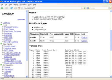
This section displays the time the DCM last rebooted and calculates how long it has been running since that time.
This section reports the current status of the DCM's storage media.
First, the DCM reports whether the disk is currently powered, and whether the heater is switched on.
Next is a table showing each file system in use by the DCM, with its size and current usage (in Mb and as a percentage.) To see the files in each file system, click Explore.
A standard DCM has two Flash partitions mounted at /nand0 and /nand1. These are used alternately to record data. If the DCM has recently used its USB disk, this will also be shown in the table.
The DCM does not power up the USB interface specially to build this table, so if you remove the USB disk the DCM may continue to include it in the table until it attempts a disk operation.
This section, if present, reports the status of the tamper lines relayed to the DCM over an external State of Health interface:
Input State Last Closed (Low) Last Open (High)
0 open (never) Wed Jul 7 16:04:48 2004
1 open (never) Wed Jul 7 16:04:48 2004
2 open (never) Wed Jul 7 16:04:48 2004
3 open (never) Wed Jul 7 16:04:48 2004
4 open (never) Wed Jul 7 16:04:48 2004
5 closed Wed Jul 7 16:04:48 2004 (never)
6 open (never) Wed Jul 7 16:04:48 2004
7 closed Wed Jul 7 16:04:48 2004 (never)
8 closed Wed Jul 7 16:04:48 2004 (never)
9 closed (never) (never)
10 closed (never) (never)
11 closed (never) (never)
12 closed (never) (never)
13 closed (never) (never)
14 closed (never) (never)
15 closed (never) (never)
The columns in the table give, in turn, the current state of each switch and when it was last observed to be in each state. The above example shows a typical reading for a set of 9 tamper switches that have not triggered: the normally-closed switches show the current time under “Last Closed”, and the normally-open switches under “Last Open”. All other fields show (never), indicating that no switches have been observed in the “wrong” state since the DCM was last booted.
This section displays basic information about the DCM's network setup. It is identical to the output from the Linux ifconfig program. A typical reading might look like this:
eth0 Link encap:Ethernet HWaddr 00:D0:1F:34:EB:08
inet addr:192.168.0.46 Bcast:192.168.0.255 Mask:255.255.255.0
UP BROADCAST RUNNING MULTICAST MTU:1500 Metric:1
RX packets:3619 errors:0 dropped:0 overruns:0 frame:0
TX packets:2453 errors:0 dropped:0 overruns:0 carrier:0
collisions:0 txqueuelen:100
RX bytes:290005 (283.2 kb) TX bytes:417231 (407.4 kb)
Interrupt:42 Base address:0x8300
For further information, see the Linux manual page for ifconfig.
This section reports the current status of the DCM's domain name resolution service. This is done by presenting the contents of the standard Linux /etc/resolv.conf file.
# eth0 begin
domain guralp.local
nameserver 192.168.0.1
nameserver 192.168.0.2
# eth0 end
For further information, see the Linux manual page for resolv.conf.
Unique IDs
This section contains unique identifiers for each of the hardware boards inside the DCM.
If you have a problem with the DCM, or it seems to be damaged, we may ask you to provide us with these IDs. You should write them down and keep them safe in case you cannot access the Web server in this event.
The final section lists the software currently installed on the DCM's Linux operating system, together with each program's version number. If you need to contact Güralp Systems about any of the installed programs, you should quote the version number in your correspondence.
4.2 Process Overview
Clicking Tools – Process Overview displays a page containing a list of all the processes currently running on the DCM. The list is generated using the standard command ps.
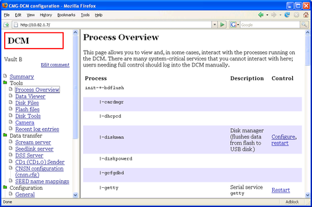
Some processes are required for the Linux operating system to function. You cannot change or restart these processes from the Process Overview page. Other processes are shown with a short description and control options.
If a Restart link is shown beside a process, clicking it will kill the process and run a new one. This is useful if a process appears to have stopped responding.
Restarting some processes may cause data transfer to be interrupted. For network services, clients will normally have to reconnect to the DCM to resume data transmission. In some cases, data may be lost. If you are unsure, contact Güralp Systems.
If a Configure link is shown beside a process, clicking it will take you to the DCM configuration options which relate to that process. For some processes, more than one link is present. For example:
Clicking the Configure link beside screamserver takes you to the Scream! server configuration page.
Clicking the Configure link beside seedrecorder edits the SEED configuration file, whilst Recording options links to the Disk configuration page.
Clicking the Mappings link beside msrecorder or slserver (the MiniSEED and SeedLink services, respectively) takes you to the SEED name mappings page.
4.3 Data Viewer
The Data viewer page uses a simple Java applet to enable you to check that the DCM is receiving data correctly. Your browser must have Java installed for you to be able to do this.
The data viewer is not intended to be a fully functional data visualisation tool. Scream! and similar software packages offer a full range of facilities for displaying and manipulating seismic data, either as it arrives or from stored data files.
The main part of the display shows a selection of the data streams being recorded, whilst the bars at the top and bottom allow you to control what is displayed, and in what manner:
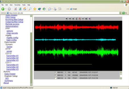
If you cannot see any data in the Data Viewer, you should check first that
some streams have been checked in the lower portion of the applet, and
the data has been offset correctly. You can automatically zero the streams by clicking on the icon depicting a “0” and a sine wave in the icon bar. Otherwise, you can zoom out until the streams are visible.
The bar at the top of the applet allows you to alter how the data is displayed. If you are familiar with Güralp Systems' Scream! package, you will recognise the icons in use here. There are:
four icons allowing you to alter the X and Y scaling factors of the graph (from left to right: magnify X, reduce X, magnify Y, and reduce Y)
a bandpass filter toggle (not currently available),
a toggle to display the endpoints of each GCF block as a white line,
a pause button, which will cause the viewer to stop scrolling as it receives new data, and
a zeroing button, which attempts to centre all the selected streams in the display.
Below the display is a list of all the streams currently being recorded by the DCM. Each has a checkbox indicating whether that stream is currently being displayed.
To the right of the checkboxes, you are given information about each stream, similar to that found in the main window of Scream!. The information provided is:
The ID of the stream (six characters long);
The compression code corresponding to the bit depth of the data. 0 = 8-bit data, 1 = 16-bit data, 2 = 24-bit data, and 3 = 32-bit data;
A recent FIC for the data. The FIC gives a rough idea of the magnitude of the signal being received.
Finally, the time the most recent data block was received, including, in brackets, the day number within the year (1 = January 1, etc.)
4.4 Data/Status Summary
This link displays information about the data streams being received by the DCM.
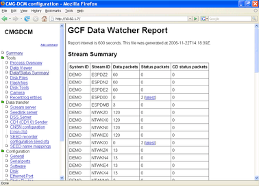
This page is updated every 10 minutes. If you make a change to your installation, you will need to wait 10 minutes before it will be reflected in this page.
At the top of the page is a Stream Summary table. This table lists all the data streams which the DCM has received in the last 10 minutes.
The first two columns are the System ID and Stream ID for the stream.
The third column is the number of data blocks which were received in the last 10 minutes. The number you should expect here depends on the sample rate and the compression level of your data.
For example, a 100 samples/s stream at 16-bit compression (moderate noise/activity), will contain 5 seconds of data in each block, so 120 blocks of data would be generated in 10 minutes.
The fourth column is the number of status blocks received in the last 10 minutes. Click on Latest to show the content of the most recent status block for that stream.
The last column is the number of CD status blocks received in the last 10 minutes. Digitizers do not output CD status blocks by default, so this column will be zero unless you have reconfigured your digitizer.
Below the stream table, the DCM prints out the content of the latest block produced by each status stream. You can use this to check on the health of your digitizer.
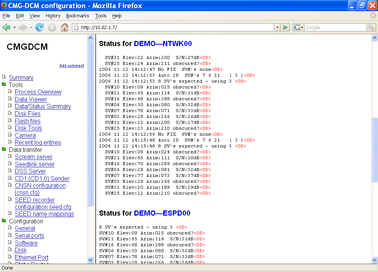
Finally, at the bottom of the page, is a table headed Shared Memory Diagnostics. This table lists the number of blocks which have passed through the DCM's internal shared memory areas. One shared memory space is allocated to each input port, but extra areas may also exist.
The entries in this table give the key index of each shared memory area, its name (if it has one – this may be taken from its allocated port), and the number of data, status and CD blocks received.
The “Bad blocks” column reports how many corrupt blocks have been detected in this shared memory area. A “bad block” is either one which could not be parsed, or one whose checksums do not match the data. Bad blocks are noted, but not discarded.
4.5 Disk files
This link allows you to browse through any files currently on the DCM's primary hard disk.
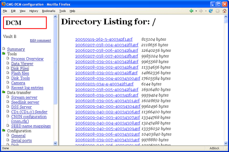
The name of each file is shown, together with its size. If there are directories on the disk, they are shown at the end of the list. The amount of free space on the disk is also displayed.
Click on a link to download a file or enter a directory.
If no suitable storage medium can be found, the module will report the error Failed to open USB disk.
4.6 Flash files
This link opens a page similar to Disk files, but which explores the DCM's internal Flash memory.
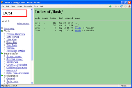
The two directories nand0 and nand1 denote the two regions of Flash memory used by the DCM to store data. Click on one of them to view the files.
4.7 Disk tools
The buttons on the Disk tools page allow you to perform some important actions on the DCM's primary hard disk.
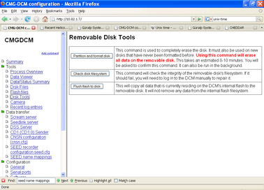
By default, the module looks for a connected USB hard disk to use as its primary storage medium. If no suitable storage medium can be found, you will see the message Failed to find a USB disk when you attempt to perform any of these actions.
Before using the CMG-DCM you should ensure that its primary hard disk is ready to receive data by partitioning and formatting it. The DCM uses a special journalling format for the hard disk which is designed to maintain the integrity of your data at all times.
The hard disk is guaranteed to contain a FAT32-compatible filesystem, even if a write operation fails or is aborted suddenly.
To format the disk, click Partition and format disk. You will be taken to a confirmation page.
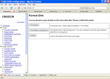
Click Format disk to format the disk and display progress. This operation takes around 10 minutes. You must not close the browser window or navigate elsewhere whilst you are doing this. Closing the browser window will abort the operation and leave you with a partially-formatted disk.
If you want to close the browser window or perform other tasks, click Format disk in background. The DCM will format the disk but will not display its progress. You should expect it to finish in around 10 minutes.
Whilst the disk is formatting, you will not be able to access it from other parts of the Web page (e.g. Disk files). If you try, the DCM will report Disk is already in use.
Click Cancel, or navigate elsewhere, to cancel the format.
Clicking on this button will verify the integrity of the hard disk's filesystem. It is recommended that you do this immediately after installing the device.
Clicking on this button will cause the DCM to dump the current contents of its Flash memory to the hard disk, thus synchronizing it with the most current data. If you want to remove or replace the DCM's hard disk, using this tool will ensure that the outgoing disk is up-to-date.
Flush flash does not remove data from the DCM's on-board Flash memory. If you Flush flash and then swap hard disks, the data remaining in memory will later be written out to the new hard disk, causing some overlap between it and the old disk.
Whilst the DCM is copying the contents of the Flash memory to disk, you will be shown a log of its progress. The USB interface allows data transfer at a speed of around 100 Kb/s, so large files may take several minutes to complete. If an error occurs at any point, it will be marked in red.
4.8 Camera
If you have attached a compatible camera to the external USB port of the DCM, clicking on this link will show the current view from the installation site. A new image is retrieved every 12 seconds, or whenever you reload the page. Güralp Systems can supply a compatible camera with the DCM, although any STV0680-based device can be used.
4.9 Recent Log Entries
This link displays the most recent 300 entries written to the DCM's internal log file.
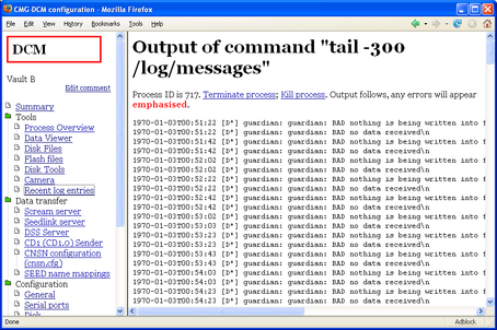
Each entry includes, in order:
the date and time of the log message,
a code [Xx] describing the type of program and the importance of the message (e.g. all errors have E as the second letter: see the Linux man page for syslog for full details),
the name of the program (e.g. guardian_log) which generated the message,
the text of the message.