Chapter 5. Installation
5.1 Pre-deployment operations
Before the deployment, make sure that the equipment works correctly. Test the connectivity of the digitiser via Ethernet and serial connection, the control functionalities including the sensor centring, data transmission, recording and download using the Maris test cable plugged into the MIN-K connector.
Caution: The MIN-K connector only allows use of 10BASE-T and 100BASE-TX networks, not 1000BASE-T. There could be some issues regarding link negotiation if the Maris is connected to a switch with Gigabit Ethernet.
Note: The 48 V power pigtail cable included in the test cable cannot be used to power up the stand-alone Maris system. The power is provided by the batteries.
In order to test the system on land, a single battery pack is sufficient. However: To achieve the maximum deployment time, it is important to fully charge all the battery packs before the deployment. Once fully charged, we suggest only running the system with all battery packs connected, in order to keep them balanced.
5.1.1 Battery charging
Warning: Never remove more than one dummy caps from the power connectors of the Minimus canister at any one time. This is because voltage is present in all of the connectors, even when only one of the batteries is connected. This design choice is necessary to reduce the power consumption.
We recommend topping up the batteries immediately prior to deployment in order to maximise the charge storage.
The charge status can be calculated by monitoring the current at the start, during, and at the end of charging.
Warning: During charging, the battery cells can release gasses which can build up inside the casing. Therefore, before charging, we advise unscrewing the ventilation screw located on the top of the battery canister. Please be aware that when this screw is open, no foreign material (e.g. fluid, dust, particles) should be allowed to enter into the canister. We recommend only opening this ventilation when the instrument is in a dry, dust-free and well-ventilated area.
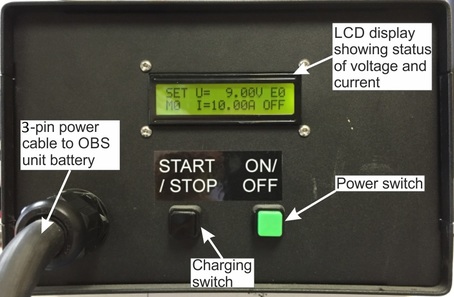
The front panel of the battery charging unit is shown below:
Batteries should be charged according to the following procedure:
Unscrew and remove the 3-pin connector of cable CAS-OBS-0144 from the battery module. Replace it with the similar cable that is attached to the battery charger.
Apply power to the IEC inlet at the rear of the battery charger unit and turn on using the switch at the rear of the charging unit.
Press the ON/OFF switch at the front of the unit to switch the charging unit on. The display will light up.
Press the START/STOP button.
The display shows the charging profile where:
I represents the current flowing into the battery pack (limited to 10 A maximum); and
V represents the charging voltage at the battery (limited to 9 V maximum).
The total charge applied is shown in the mAh / Ah part of the display. This is a cumulative running total so, if you want to know the total amount of charge added, record the start value before starting a cycle.
At the beginning of theprocess, charging will begin in CC (Constant Current) mode with 10 A being delivered to the battery.
As battery reaches 80% charge, the current will reduce as the voltage is limited to 9 V.
Once the current drops to zero, the battery is fully charged. At this point, record the charge in mAh or Ah and subtract the equivalent starting value (Step 6) to find the total charge that has been put into the battery.
Typically, a complete charge from a fully-discharged battery to fully-charged will require 385 Ah.
Caution: If you turn the charger off at the mains, with the battery still connected and the front, green power switch is left on, the display will remain lit up. This will then slowly discharge the battery, so avoid leaving it in this state for any extended period of time.
Note: The complete process of charging every battery for a single Maris system will take approximately 39 hours.
5.1.2 Clock synchronisation
The Maris OBS has a temperature-compensated real-time clock which is used for time-stamping recorded data. The clock must be synchronised to GNSS time before each deployment. When the system is retrieved at the end of the deployment, the GNSS receiver should be reconnected. This allows the internal clock to be compared to GNSS time and the drift calculated (see section 5.3). This value can be used to apply a first-order linear correction to the time-stamps of the data to compensate for drift. (Such correction is not currently provided by Güralp software).
Connect via Ethernet to the digitiser using the MIN-K connector.
Connect the GNSS receiver using the connector in the top lid of the Minimus canister.
Launch Discovery and open the Minimus web-page.
Wait until the GNSS stability reaches 100 %
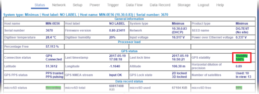
and then keep the GNSS connected for a further few minutes, before clicking the “Deploy” button (see section 4.2.7).
Disconnect the GNSS reciver and plug in the dummy cap in its place.
5.1.3 Enable the power save mode
The last step before the deployment is to enable the power-save mode:
Connect via Ethernet to the digitiser using the MIN-K connector.
Follow the instructions in section 4.2.7 at page 21.
Disconnect the cable from the MIN-K connector of the digitiser canister and plug the Titanium protective cap before the deployment.
5.2 Deployment procedure
Warning: The overall weight of the Maris system in air is of 279.6 kg (133.5 kg in water). Each battery weighs 31 kg in air (14.8 kg in water), the Minimus canister weighs 26 kg in air (12.6 kg in water) and the sensor weighs 5.6 kg in air (2.5 kg in water).
It is recommended that the Maris is ony deplyed by trained personel. For this reason, no physical deployment details are provided in this document.
5.3 Recovery procedure
After physical recovery, the following steps should be performed:
Remove the GNSS dummy cap and replace with the GNSS receiver.
Remove the Titanium protective cap from the MIN-K connector and plug in the test cable.
Plug in the 9-pin COM port of the test cable on a PC/laptop and use a terminal emulator to send the command powersave off. This will power on the GNSS and calculate the clock drift (once the GNSS receiver has acquired a lock). The drift will be reported on the terminal and will also be stored in the SD card, in the system.log file, as shown in the example below:
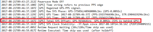
The powersave off command also re-enables the Ethernet interface. By accessing the Minimus web page from a PC, it will be possible to download the data using the procedure described in section 4.2.4.3.